9.16.
This method requires the use of two pins, C-clamps, slip gauges and a dial indicator. The work is clamped on the surface plate with C-clamps.
Two pins of equal diameter are placed against the inside edge of the circle and the intervening space between the pins is filled in with a combination of slip gauges. It is not necessary that combination of slip gauges and pins should fit into the space exactly but a slight amount of play can be tolerated and in that case the slip gauges and one pin can swing around the second pin. A dial indicator is clamped in such a position as to register arc of the pin and slip gauges when they swing from side to side as shown in Fig. 9.19.
Let the diameter of pins be d and length of slip gauges I and swing noted by dial indicator S.
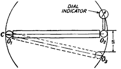
Fig. 9.19

Fig. 9.20

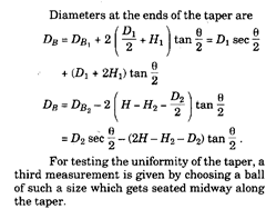
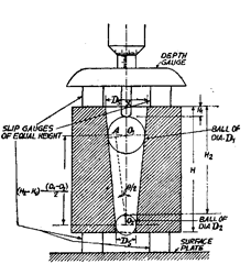
Fig. 9.21
(i) In this method, practical precautions have to be taken in order to prevent the balls jamming in the gauge. The weight of the ball and the force applied to it by the micrometer can cause appreciable axial movement. For this pur-
pose the gauge may be held vertically, with one finger through the small end and the ball gently lowered into position. As the angle of taper is small, if care is taken, relatively coarse height
measurements give high accuracy of diameter measurement.
(ii) In the previous method, sometimes it so happens, particularly with slow tapers that two balls can’t be found to fit in the taper gauge at suitable positions. This difficulty can be overcome by putting a cylinder between such ball and one side of the taper gauge. In this method too, there being point contact between balls, cylinders and gauge, the compression effect must be minimised.
![]()
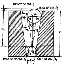
Fig. 9.22
![]()
…(f)
![]()
…(ii)
![]()
…(at)
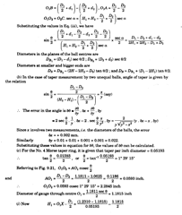

Problem 9.3.
(a) Describe the method of measuring included angle by three discs method, (b) Also derive expressions for the possible errors likely to occur in the measurement. Solution, (a) In this method, three hard steel discs of rollers of equal diameter are
arranged as shown in Fig. 9.24 (a). The distance H is measured by a depth micrometer gauge or a straight edge and slip eauees.
![]()
...(i)
Though theoretically this method can be used for ingles between 180 degrees and about 60 degrees, but “or angles below about 90 degrees, it is preferable to neasure the gap between the two outer discs (L) as shown in Fie. 9.24 (b). in which case

…(ii)
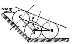
Fig. 9.24 (a)
For angles between 90° and 180°
For angles less than 60° it may be preferable to use only two discs as shown in Fig. 9.24 (c) and the distance L is measured by slip gauges. Referring to Fig. 9.24 (c), obviously BC = L.
![]()
…(iii)
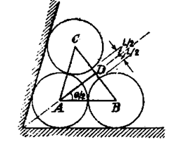
For angles between 90° and 60°
Fig. 9.24 (b)
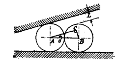
Fie. 9.24 (c)
For angles below 60°
(b) Possible errors in the measured angles are determined as follows :
![]()

Problem 9.4.
Describe the various methods used to measure the radius of a circular arc on a component, when the centre of the circle is not accessible and the radius is large in comparison with the dimensions of the component.
Solution.
One of the simplest method is such cases is to use surface plate and rollers. Two set-ups are possible as shown in Fie. 9.25 (a) and (6).
In the first method, the work is placed on a surface plate and two equal rollers of diameter (d) are placed in position as shown in Fig. 9.25 (a). The distance over the rollers (L) is measured by vernier gauge. Let R be the radius of circular arc.
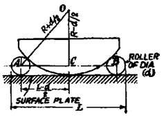
Fig. 9.25 (a)

![]()
In the other method [Fig. 9.25 (6)], two rollers of equal diameter (d) are set up against a straight edge and clamped on a surface plate with a certain standard end gauge of length (L) set accurately between them. The end gauge is then removed and the work is held against the opposite sides of the rollers. Slip gauges of appropriate dimension (Z) are then inserted between the work and the straight edge. Let R be the radius of the work.
In Fig. 9.25 (b), DE = dimension of slip gauges inserted between work and the straight edge = I.

…(*)
CO = FO-FC = R + ^-d + l
CO + FO=R+^ + R+^-d + l = 2R + l
Substituting the values in equation (i) |^)^j = (d-/)(2R + Z).
Knowing the values of L, d and I ; and substituting them in this equation, the value of R can be found out.
In such a test, uniformity of radius is checked by moving the work round to various positions and noting any variations in slip-gauges needed.
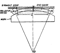
Fig. 9.25 (6)
Problem 9.6
. Describe three methods to determine the diameters of parallel bores using steel balls, dial indicator and slip gauge.
Solution,
(i) The job to be measured is assumed to have its one face perpendicular to the axis of job. The balls of known diameters d\ and d2 are kept one over the other in bore as shown in Fig. 9.26. The values of d x and d2 should be greater than diameter of bore. The height

Fig. 9.26

Fig. 9.27
of high point of upper ball from surface plate is measured with the help of slip gauges and dial indicator. The slip blocks are piled such that the dial indicator reading at slip blocks and highest point of ball is same. Knowing distance H, the diameter of bore can be calculated as follows :
![]()
(ii) The diameter of bore can also be found by using three equal balls of diameter (d) less than half of the bore diameter and a fourth ball of any diameter (D) but less than 0.75 of the bore diameter. Balls are placed as shown in Fig. 9.27. The height of highest point of upper ball is measured accurately with the help of slip gauge and dial mounted on a height gauge. It will be appreciated that bigger ball of diameter D resting over three balls of equal diameter d will always be located in the centre of bore, and therefore,
![]()
(iii) Figs. 9.28 and 9.29 show another way for checking diameter of bore. Here 2 balls [or rollers are taken such that (di + d2) is less than the diameter of bore. Suitable slip blocks are inserted between the balls (or rollers). Diameter of bore = (d\ + d2) + slip inserted.
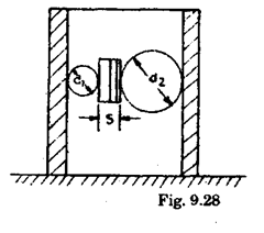
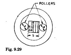
This method is specially useful when :
(a) The thickness of job is less.
(b) Required combinations of balls are not available.
(c) End surface of job is not perpendicular to the axis of the job.
Problem 9.7.
Describe a method to measure radius on a part.
Solution.
Quite often it is required to check the radius of a gauge or template. The special methods are generally adopted according to the design of gauge of template and a suitable reference is chosen. For measuring big radius the special method using balls and rollers is the only way. Rollers are found more convenient to use.

Fig. 9.30
Fig. 9.30 shows a small template whose radius is to be determined. It has been placed on a surface plate and an adjacent surface is touching the straight block. Height of template, H is measured by slip gauges and height gauge. Roller of known diameter is placed and allowed to rest in between the straight block and radius, and hi is measured over the roller.
![]()
From the above expression R can be calculated. For cross checking the results, other roller of known diameter is taken and R is again calculated.
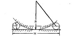
Fig. 9.31
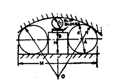
Fig. 9.32
External big radius of cylindrical form or spherical forms can be calculated using standard balls or rollers. Fig. 9.31 represents the way of checking external radius.
Two rollers of equal diameters are allowed to take position touching the surface plate and the curved surface. The size over these rollers is measured and radius R can be calculated as follows :
![]()
In above expression only R is unknown, which can be calculated easily.
![]()
In above expression only R is unknown which can be calculated.
Problem 9.8.
Check smaller and larger diameters of tapered gauge within an accuracy of- 0.001 mm without using sophisticated measuring instruments. The edges have been made round by giving radius; so the imaginary smaller and larger diameters have to be measured.
Solution.
The diameters can be checked by using one precision ball or roller of known diameter. For obtaining high accuracy it is essential that only one set-up be used to take readings. Set-up is shown in Fig. 9.33. Slip gauges, S2 and Si are so adjusted that upper taper
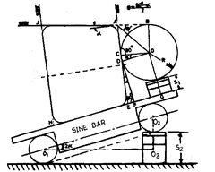
Fig. 9.33
portion of gauge is exactly horizontal and the highest point of the roller of radius R over slip gauge S| i« in lm> with upper taper surface of gauge.
The following calculation will give required results
![]()
So the angle a can be calculated. The smaller diameter
![]()
Knowing smaller diameter, the larger diameter can be known by measuring height of thejob. .
Problem 9.9.
Describe method to determine the depth (h), width (w) and angle (q) of the dovetail shown in Fig. 9.34.
Solution.
For determining depth h, place a mandrel over top surface AB and try suitable slip gauge combination that would just pass under the mandrel and bottom surface of dovetail. The slip gauge pile should be tried at several positions to obtain average value of h.

Fig. 9.34
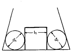
Fig. 9.35
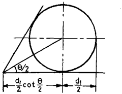
Fig. 9.36
To determine the values of w, 8, place two rollers of diameter dx in vees and insert suitable gauge pile of length lx in between the space. Similarly place other big rollers of diameter d2 and determine length Z2 of slip gauge to fill up the remaining space.

Problem 9.10.
A cylindrical ring gauge, having its end face square to its axis stands on a lapped surface plate and its diameter is measured by placing three balls of 10 mm diameter in the gauge, two of them resting on the plate and the third making contact with other two and the bore of the gauge only. The latter ball lies 2.50 mm above the other two. Determine the diameter of the gauge.
What is the limitation of this method ?
Solution.
Let A, B and C be the centres of the three balls. Let C be the projection of centre C on a horizontal plane passing through the centres A and B.
The circumscribing circle of the triangle formed by joining points A, B and C" will be 10 mm smaller in diameter than the diameter of gauge.
![]()

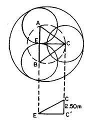
Plan of the set up.
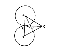
View through a horizontal plane passing through the centres A and B.
Fig. 9.37
![]()
![]()
![]()
The limitation of this method is that this does not measure a true diameter in one plane and variations in diameter along and round the cylinder will affect accuracy. This also does not detect the ovality. However if the height difference between the ball is quite small and the cylinder is fairly uniform in diameter, then quite good accuracy can be obtained and any error in height measurement will give only small errors in diameter.
Problem 9.11.
Obtain an expression for the measurement of the diameter of a cylindrical ring using two balls of equal diameter dj less than the radius of the gauge and another large ball of diameter d2 which will rest on the two smaller balls and the ball of the gauge.
Solution.
Let A, B and C be the exact centres of three balls and C" the projection of C on a horizontal plane passing through centres A and B. Next we can locate a circumscribing circle which is concentric with the diameter to be measured and this passes through the centres of the lower balls and through another point which is perpendicular on horizontal plane through a point at a distance along the diameter of the larger ball from its point of contact, equal to the radius of the smaller balls.
Let E be such a point and E' its projection on the horizontal plane through A and B
![]()

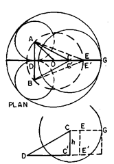
Fig. 9.38
Problem 9.12.
Describe a fixed roller type micrometer used to determine the radii of convex and concave surfaces. Derive the
mathematical relationship
.
Solution.
Fig. 9.39 shows a fixed roller type mircometer which is used to determine the radii of both convex and concave arcs. Let d be the diameter of rollers and I the distance between the centre lines of the roller.
The instrument is first placed on a true straight edge and a reading of the micrometer taken with the spindle end in contact with the straight edge. It is then placed on the arc and another reading taken on this. The difference between the two readings is the height of the arc above the tangent to the rollers, i.e. dimension h2.

Fig. 9.39
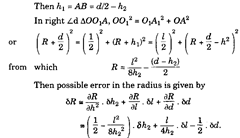
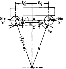
Fig. 9.40
Problem 9.13.
Describe a method to determine the radius of convex surface using V-plate. What are the limitations and disadvantages of this method ?
Solution.
When measuring concave arcs, a ball end is fitted over the spindle and the
Z2 (d + h2)
formula for the radius then becomes R = —-o +-z— .
8h2 2
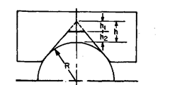
The radius of convex surface can be determined from a measurement of the distance from the arc to the apex of a Vee-piece resting against it [Refer Fig. 9.41 (a)]
![]()

(a)
(b)
Fig. 9.41
The value of l/(cosec 9/2 -1) is usually marked on the instrument so that the radius can be easily calculated by multiplying the distance h by this constant.
As it is very difficult to measure distance from convex surface upto apex of the vee with sufficient accuracy, sometimes a flat is formed in the vee-angle and slip gauges are used to measure the distance between arc and the flat. The latter arrangement is shown in Fig. 9.41 (b). In this case,
![]()
In above expression–—- is constant and only variable is ht.
cosec — – 1
![]()
By referring to a table of cosecants, it will be seen that the value of (cosec 6/2 – 1) varies rapidly according to the value 8, and consequently the error in the radius obtained by means of the above expression is considerably influenced by the angle of the vee-piece. The instrument used for any particular workpiece should therefore be chosen so that it embraces as much of the arc as possible in order it make the angle small. This means that several instruments are needed for work of different sizes and this is the main disadvantages of this type of instrument.
Problem 9.15.
The radius of an arc was measured by allowing a 20 mm diameter roller to oscillate to and fro on it and the time for 25 oscillations was noted at 56.25 sec. Determine the radius.
Solution.
When a roller is allowed to oscillate about its equilibrium position by placing it on an arc, then it executes S.H.M. and the radius of arci?, radius of roller r and time of one oscillation T are related by the relation.
![]()
Problem 9.16.
A solid cylindrical gauge of diameter D has an inclined hole of diameter dj passing transversely through its axis at angle 6 to the axis. Devise a method to determine the height of the intersection of centre of hole from the plane end of the gauge. It can be assumed that a well-fitting plug for the hole is available.
Solution.
Two rollers of diameter di and d2 with their centres Oi and 02 are placed in between the space between plug and the cylindrical gauge as shown in Fig. 9.44 and the height hx and h2 over the top surface from the bottom surface are measured.
If C is point where plug surface intersects with the outer surface of gauge then line COi02 bisects the angle 0.
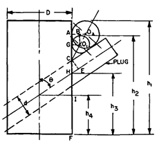
Fig. 9.44
9 a O2B
02A is J. to gauge surface and OiB is 1 OqA, :. tan — = tan 02OiB = -r-=r
d2 – d\
__2
![]()
Problem 9.17.
Describe a method to determine the angular spacing of holes of same size located radially at angle q.
Also derive the expressions for errors.
Solution.
A plug which must be a good fit for the hole is inserted in each hole and rollers are placed in positions as shown in Fig. 9.45. The dimension L over the rollers is measured and from this, together with the diameters of the pins (P), rollers (d) and shaft CD), the angle q can be calculated as follows.

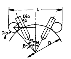
Fig. 9.45
Assuming the centre lines of the holes to be truly radial, the accuracy to which the angle can be measured is given by the following expression. 58 = 2(8a — 56)
![]()
Problem 9.18.
Describe an arrangement for measuring the angle of a hole drilled at an angle to a flat surface. Also derive an expression for the same and the error likely to be introduced on account of error in measuring distances and diameters of the rollers etc.
Solution.
The arrangement for the measurement of angle is shown in Fig. 9.46. A closely fitting plug is inserted into the hole and rigid block fixed on the horizontal surface. Two rollers of different diameters are required and measurements are made with these pi aced, in turn, in the position shown.
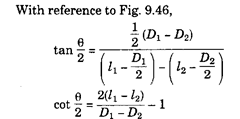
The possible error in the angle q is quite small.
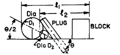
Fig. 9.46

Problem 9.19.
Devise a method to measure the angular spacing of a spline shaft having splines with parallel faces.
Solution.
Fig. 9.47 shows a cross-section of the shaft and Fig. 9.48 the method of measuring the angular spacing. It is first necessary to measure the root diameter of the shaft and width of each spline. Then, referring to Fig. 9.48.
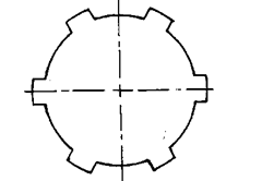
Fig. 9.47
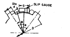
Fig. 9.48
![]()
Problem 9.21.
Describe a suitable method to determine the diameter of small end of a taper gauge.
Solution.
Fig. 9.50 shows the arrangement to determine small end diameter of a taper plug gauge in which the gauge is mounted over a sine bar. The height of slip gauge pile below the sine bar is adjusted so that the upper surface of taper plug is horizontal. A roller having its diameter slightly less than the small end diameter is then placed at the end of the plug gauge and slip gauges of such length are inserted between the roller and end of plug gauge so that the dial reading over the gauge and roller is same.
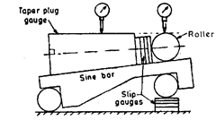
Fig. 9.50

Fig. 9.51
![]()
