2.5.
The foundation of all geometric accuracy and indeed of all dimensional measurement is the
flat plane, which is usually provided in the workshops and inspection laboratories by the surface
plate.
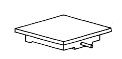
Fig. 2.18. Cast iron surface plate—
The working surface.
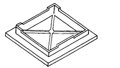
Fig. 2.19. Cast iron surface plate—
the underside.
Figs. 2.18 and 2..19 show a typical cast iron surface plate and its working surface and the
underneath. Most surface plates are rectangular, having 4 : 3 length: width ratio. Square or round
plates are geometrically most correct for creating a flat plane by the three plate method.
The commonly used cast iron surface plates have special ribbing and structural formations
under the surface so that these will be as light in weight as possible and yet will not warp or settle
after the castings have aged, (Refer Fig. 2.20). In fact, the true plane of the surface is not machined
and “scraped” until it has really aged and all internal stresses have subsided. During the last few
years true, flat, smooth surfaces have been polished on granite blocks and granite surface plates
have found easy popularity.
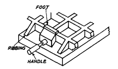
Fig. 2.20. Underside ribbing
of a surface plate.
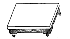
Fig. 2.21. Surface Plate.
The iron plate has the advantage of allowing a certain amount of wringing and surface or
edges are not readily chipped out if something is dropped on it. The glass plate will shatter, or break
and be destroyed if heavy pieces are dropped on it.
Surface plate (refer Fig. 2.21) forms the basis of measurement and is a must for metrology
laboratory where inspection work is carried out. It provides a datum or reference surface for
measurements. It is also used to check the flatness of another surface. It has got a flat surface and
all other measuring instruments having flat base can be placed on the surface plate. The big surface
plate generally rests on four levelling screws with the help of which its surface can always-be kept
horizontal. This is invariably made of cast iron, and in manufacture, is artificially aged to set free
from all internal stresses. After this, its dimensions will never change with time. At the bottom it
is strengthened by ribs. The top surface is scraped to true flatness. A wooden cover isjaiways placed
over it, when not in use. When in use the whole surface of the plate must be used and not the centre
or corners in erder to have uniform wear. Grease must be applied to top surface when not in use
for long time. A regular check for flatness must be made after regular intervals.
It is well known fact that all precision measurements start from flat surfaces and that
without the aid of an accurate plane surface it is impossible to do any precise mechanical work and
that the surface plate, whose upper face is flat within close limits of accuracy, is of fundamental
importance for precision measurements. The surface plate serves two important purposes, viz. it is
used as datum plane for taking accurate linear and angular measurements, and with the aid of
suitable marking compound, it serves for testing the degree of flatness of other surfaces. For very
accurate work it is very essential that the form and dimensions of a surface plate must be such that
distortion or deflection is reduced to a minimum even under comparatively heavy loads. For this
reason it is customary to reinforce the plate proper by the provision of a frame and ribbing of
considerable depth. The standard available sizes of the surface plates vary from 100 x 100 mm to
2000 x 1000 mm in about 13 ranges. Generally surface plates upto size of 1000 x 630 are provided
with three supporting feet and above it, either 3 or 4 feet. If a surface has more than 3 feet, the
supporting surface on which the feet rest ; a special stand or bench should be provided with
adjustment to ensure that all the feet bear evenly. Moreover, it is also desirable that the bearing
surfaces should be smoothly machined in order to permit slight movement with change in tempera-
ture. It is recommended to provide a projection of at least 25 mm on all sides of the surface plates
measuring 250 x 250 or over. The undersides of these projections should be machined properly and
reasonably flat to facilitate the clamping of work or measuring instruments. The threaded holes
can also be provided in the plate without affecting the accuracy if the drilling and tapping operations
are carried out before the surface is finished.
The four edges of precision plates are usually finished straight and square to each other
within the accuracy of 0.08 mm per metre. The upper surfaces of the plates are finished by scraping
operation. The idea of the accuracy of the flatness of the top surface can be had from the fact that
the maximum permissible error from mean true plane (for a surface plate of diagonal 150 mm) is
allowed between ± 0.002 to ± 0.005 mm ; and for surface plate of diagonal 2000 mm, maximum
permissible error from mean true plane is allowed to vary between ± 0.02 to ± 0.04 mm. Further in
addition to the conforming of above tolerances of whole of the top surface of the plate, bearing area
of any local area from the mean true plane of that local area should not deviate by more than 0.01
mm per metre to 0.025 mm per meter. It is also very essential that the proportion of the area of the
surface plate represented by high spots, on which another flat surface would rest, should be
comparatively small and should not be more than 10 to 20%.
2.5.1.
Material for Surface Plate.
The surface plates should be made from a material
which will provide a high degree of rigidity and freedom from warping and capable of taking a high
finish and the surface must be resistant to wear. Most commonly used material for this purpose is
either the plain or alloyed close-grained cast iron of good quality. After casting and rough machining
and prior to finishing operation, the plates should be allowed to age either naturally by allowing a
suitable period of time to elapse or by proper heat treatment in order to relieve the internal stresses.
The composition of most commonly used plain cast iron and alloy cast iron for surface plates
are:
| Plain Cast Iron | Alloy Cast Iron | ||
| Total carbon | …3 to 3.5% | Total carbon | …2.8 to 3.2% |
| Combined carbon | …0.4 to 0.7% | Silicon | …0.8 to 1.5% |
| Manganese | …0.5 to 1.2% | Manganese | …0.6 to 1.0% |
| Silicon | …1.0 to 1.2% | Sulphur | …0.12% (max) |
| Sulphur | …0.15% (max) | Phosphorus | …0.33% (max) |
| Phosphorus | …1.2% (max) | Nickel | …1.4 to 1.6% |
| Chromium | 0.4 to 0.6% |
The heat treatment of the surface plates made of above materials is carried out as follows :
The plates are placed in an annealing furnace and heated upto 450 to 500°C and maintained
at this temperature for about 3 hours or longer depending on the mass of the casting. The castings
are protected from the direct heat of the flames by means of suitable baffle plates and heating should
be as uniform as possible throughout. In case of small castings, more uniform heating is obtained
by packing the casting in iron fillings in boxes. Then plate is allowed to cool gradually in the furnace
itself without opening the doors. It is preferable to hold the temperature at 400°C for about an hour
during cooling.
Apart from cast iron, surface plates are also made of non-metallic substances, viz. granite
and glass. Metallic objects like height gauges, squares etc. can be easily slid over their surface.
Their advantages are : These are more rigid for same depth. Corrosion is virtually absent. A big
problem with C.I. surface plate is that any damage to surface throws up a projecting burr but in
case of granite and glass surface plates it causes indentation only.
2.5.2.
Manufacture of cast iron surface plates.
It is not uncommon for a cast iron plate
to lose its straightness, etc. over a period of time if certain precautions are not taken during its
manufacture and use. The composition of the iron is the first thing to be taken care of since the
proper composition improves machinability, wear qualities and the quality of the scraped surface.
It is also important to remember that stability of the iron depends mostly on slow, uniform cooling
in the mould after casting, which in turn, depends on the moulds of proper design, and on allowing
sufficient time for complete cooling before the casting is exposed to air.
The equilibrium of cast iron part can be altered during machining particularly when
substantial amount of material (outer skin) is removed. Thus before the finish cut, the piece must
be allowed to relax by release of the clamps, the parts then properly supported and re-clamped
without bending. It is also observed that single-point planing produces least springing and
machining distortion in piece (compared to machining by milling).
Large cast iron section can easily bend when subjected to a load and elastic deflections may
occur. Deflection can be minimised by adopting proper design and supports.
Lastly, the geometric relationships are not affected by the ambient temperature if it is steady.
Only temperature deviations cause problem, emphasing the need for maintaining temperature at
constant value.
2.5.3.
Sizes and Accuracy of Surface Plates.
According to IS : 2285—1963, the cast iron
surface plates are classified into two grades (grade I and grade II). The recommended size of the
surface plates and the maximum permissible departure from flatness of bearing area are given
below [Refer Fig. 2.22].
| Nominal size | Minimum | m x n | h | s | Maximum permisible departure | |
| a x 6 | thickness | mm | mm | mm | from flatness of bearing area | |
| mm | of top (t) | in microns | ||||
| Grade I | Grade II | |||||
| 100 x100 | 9 | 80 x 80 | 25 | 5 | 2.5 | 10 |
| 160 x 100 | CO | 70 x80 | 25 | 5 | 3.5 | 14 |
| 160 x160 | 9 | 64 x64 | 25 | 5 | 3.5 | 14 |
| 250 x 160 | 12 | 73 x 64 | 40 | 5 | 3.5 | 14 |
| 250 x 250 | 15 | 100 x100 | 40 | co | 5.0 | 20 |
| 400 x 250 | 15 | 117 x100 | 50 | 8 | 7.5 | 30 |
| 400 x 400 | 18 | 107 x107 | 50 | 8 | 7.5 | 30 |
| 630 x 400 | 18 | 137 x107 | 80 | 9 | 7.5 | 30 |
| 630 x 630 | 21 | 126 x126 | 80 | 9 | 7.5 | 30 |
| 1000 x 630 | 24 | 175 x126 | 125 | 12 | 10.0 | 40 |
| 1000 x1000 | 30 | 200 x 200 | 160 | 15 | 12.5 | 50 |
| 1600 x1000 | 30 | 280 x 200 | 200 | 18 | 17.5 | 70 |
| 2000 x 2000 | 36 | 300 x 200 | 250 | 18 | 20.0 | 85 |
In addition to the above provision, the
departure from flatness should conform to the
following requirements also for sizes 630 x 400
mm and larger:
Grade I. Maximum 5 micron over any local
area of 300 x 300 mm of plate.
Grade II. Maximum 20 micron over any
local area of 300 x 300 mm of plate.
The rigidity of grade I plates above 400 x
250 mm size should be such that when a con-
centrated load is applied at the centre of the plate
(head should cover area of 100 cm2 for smaller
plates to 500 cm2 for longer sizes of plates), the
loaded area does not deflect below the remaining
surface of the plate by more than 0.003 mm per
50 kg load.
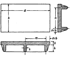
Fig. 2.22. Surface plate sizes as per BIS.
It is recommended that the top surface of grade I surface plate be finished by scraping process
and the percentage of high spots on the top surface should not be less than 20% whereas the grade
II plates should be finished by grinding operation and percentage of high spots should not be less
than 10%. The percentage area of high spots should not be more than 50% in both the cases.
2.5.4.
Principle of Flat Surface Generation.
Principle of the three-plate technique of
surface generation is commonly used for generating flat surface of surface plates. According to this
principle, it is impossible to devise any combination of mating the three surfaces together unless
they are flat.
1. Two plates can be scraped so that
they mate together without being flat, as
with plates ‘A’ and ‘B’.
2. This out-of-flatness is shown up as
soon as they are compared with plate ‘C.
3. Only if all three plates are perfectly flat can they be interchanged and still mate.
![]()
Fig. 2.23. Generation of a flat-surface.
2.5.5. Scraping of Flat Surfaces. Cast iron surfaces are finished to ahigh degree of flatness
by hand scraping method. This method requires considerable time and skill. The various steps
followed for this purpose are described below :
(i) The surface is first cast, properly heat treated and allowed to age.
(ii) The surface is then rough machined and finish planed. After rough planing, castings are
again aged either naturally or artificially and at least a month is allowed to elapse after the surface
has been finish planed.
(iii) The surface is then scraped lightly once or twice all over by progressively removing the
high spots in order to produce a smooth finish and an approximate flat surface before proceeding
to correct any small irregularities that may be present.
(iv) The surface is then scraped by applying a suitable marking compound. The most
commonly used compounds to show bearing marks are red lead, prussian blue and lampblack mixed
with lard oil.
(a) For rough scraping, first the marking compound is applied fairly generously to flat plate,
being thinned down as necessary to facilitate spreading. When an even coating has been obtained
the work to be scraped is brought in contact with the flat plate and rubbed lightly thereon, or vice
versa. The high spots thus indicated are removed by scraping and the process is repeated until fairly
uniform spotting all over the surface is obtained.
(b) Then the compound in somewhat dryer form is applied to the work to be scraped. The flat
surface is then rubbed on the work and thus the high spots produced by rubbing show up distinctly.
The amount of compound applied is gradually reduced and in later stages petrol is also mixed to
act as dryer. Finally only just enough compound is used to dull the surface without colouring it and
the true high spots are thus shown and there is no risk of false bearing indications such as may
occur if the surface plate is coloured.
(c) Ornamenting Scraped Surfaces. After the scraping operation, the surface plates are
frequently finished by processes commonly known as frosting, snow-flaking and spotting in order
to obliterate the somewhat irregular marks left by the scraping operation and to obtain pleasing
appearance. In the frosting operation, no metal is removed and thus accuracy previously attained
remains the same; its effect being manifested primarily by the manner in which the light is reflected
from the surface. The various patterns produced by frosting operation can be of the following
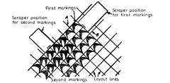
Fig. 2.24. Ornamenting scraped surface.
shapes : crescent shape, diamond frosting, evenly spaced crescent shaped marks, irregular check-
ered pattern. The method whereby evenly spaced crescent shaped marks can be readily produced
on a surface plate is shown in Fig. 2.23.
Scraped surface of an iron surface plate is found to be free from wrap, waviness or chatter.
2.5.6.
Originating Surface Plate.
This is the method of producing an accurate surface
plate without the aid of any reference plate or any measuring instruments. The method is based
on the fact that the flat surfaces are self-checking and employs the principle known as “symmetrical
distribution of errors”.
For this method of originating a surface plate, it is necessary to have three suitable castings
(say, 1, 2, 3) which have been aged and finish planed as accurately as possible. First of all the
surfaces of all the castings are scraped to a smooth finish and the marks of planing tool completely
removed. Prussian blue is then applied to plates 1 and 2, and each is roughly scraped using a wide,
flat scraper blade (the cuts being long and deep) until a reasonably good bearing distribution is
obtained. In the case of square plates, these should be successively turned 90° one to another to
reveal “twist”. The plate 3 is then roughly fitted to plate 1 by removing metal from plate 3 only and
no metal being removed from plate 1. Thus plate 3 will be an approximate duplicate of plate 2, i.e.
neither plate 2 nor 3 is perfectly flat but both have the same errors and the plate 1 is having errors
reverse of 2 and 3. As the spots become progressively more uniform and evenly spaced, a narrower
blade is used, the angle of cut is raised gradually from the horizontal, and the stroke is shortened.
The most satisfactory scraping stroke is the “half noon”, in which case the stroke starts from the
valley, reaches its greatest intensity directly on the spot, and again fades to nothing as it passes to
the other side.
On applying plates 2 and 3, the errors which were previously marked by the reverse
deficiencies of No. 1 are now duplicated and accentuated. Now plates 2 and 3 are scraped to fit into
one another, care being taken to remove as nearly as possible the same amount of metal from each
during the process. Thus these two plates will be more accurate than No. 1. The next step is to scrap
plate 1 to fit 2 and then fit plates 1 and 3 by scraping the same amount from each. In this way plates
1 and 3 are made more accurate than plate 2.
Plate 2 is then scraped to fit plate 1 after which 2 and 3 are scraped together removing the
same amount from each. This cycle is repeated until all the plates will fit one another interchan-
geably thus affording positive indication that the plates are perfectly flat.
2.5.7.
Finishing flat surfaces by hand lapping.
The lapping process is employed for
producing the flat surfaces required to possess great degree of accuracy and uniformity than can
be obtained by scraping or grinding operation. The process of lapping is carried out by rubbing the
work over the surface of a flat plate or lap made of either steel or copper where durability is the
main consideration, and of cast iron for very precision work. Very fine particles of a suitable
abrasive, which are either initially embedded in the surface of the lap or mixed with a suitable
lubricant or distributed in a thin film between the lap and the work, gradually wear down the high
spots on the work which initially bear on the lap. As the process is continued a close approximation
to true plane is obtained. It will be appreciated that as the work is moved about over the surfaces
of the lap the effect of errors in the flatness of the latter is distributed and as such the errors in the
surface of the work will be small than those of the lap. Further, the more closely the surface of the
lap approaches to a true plane, the greater will be the degree of accuracy ultimately obtainable in
the work.
If a perfectly flat lap is used for lapping the flat surface plate, then many difficulties are
encountered due to the presence of a film of oil, abrasive or air between the surfaces. The film of oil
produces a light cushioning effect, thereby allowing one surface to rock upon the other to a limited
extent. Trouble is also caused by uneven distribution of the abrasive which has a tendency to collect in
the central portion of the plate. In order to overcome the above difficulties encountered when
perfectly flat lap surfaces are employed, the surfaces of the laps are scored with small grooves of
the form indicated to the right in Fig. 2.25 and spaced about 5 to 6 mm apart so as to produce a
checkerboard pattern. These grooves allow the oil film to be pushed aside or sheared from the
surfaces thereby permitting them to come into closer contact. The grooves also provide for
ventilation so that the air pressure between the surfaces is partially relieved.

Fig. 2.25. Form of grooving for lapping plates.
The abrasive particles used for lapping purposes are of two types viz. charging and
non-charging. The non-charging abrasives (such as Turkish lapping powder, Vienna lime etc.) when
introduced between two surfaces of equal hardness remove equal amount of material from each by
abrasion when the surfaces are rubbed together. Whereas in the case of charging abrasives e.g.,
diamond dust, finely powdered emery and corundum as natural abrassives and SiC, AI2O3 as
artificial abrasive) the laps of softer material are employed because the abrasives tend to become
embedded in the surface of lap and the embedded particles projecting out of soft surface of the lap
act as innumerable small cutting edges. For obtaining best results, it is essential that particles of
abrasives be as nearly as possible uniform in size and as fine as possible in order not to produce the
irregular scratches on the surface of the work and for greater accuracy and finish.
The lapping process can be either wet or dry. In the wet process the rate of metal removal
is considerably higher whereas in the dry process a greater degree of accuracy is obtainable owing
to more intimate contact between the work and the charged lap surface. In the wet process the
abrasive is mixed with a suitable lubricant (soda water, paraffin, petrol, turpentine, machine oil
and lard oil) and a thin film is applied over the lap. Under the pressure exerted by the work the
abrasive particles tend to become embedded in the lap but there is always a surplus of oil and
abrasive on the surface. In the case of dry process, first the lap is charged by pressing or rolling the
abrasive into the surface. Though process is called dry, it is usual to apply a very slight amount of
lubricant to the lap surface.
In the lapping operation, it is most essential that an irregular rotary movement be applied
to the work in order to ensure, as far as possible, that every available part of the lay surface is
utilised to the same extent. The work, therefore, should be pushed gently round, no two consecutive
movements taking place over the same portion of the lap. If the work is only rubbed to and fro across
the middle of the lapping plate, a depression would speedily be formed and satisfactory results
cannot be expected. When irregular movement of the work takes place then it tends to distribute
the effects of any inaccuracies that may have originally been present in the lap surface. The pressure
exerted on the work should merely suffice to ensure constant contact with the lap surface. When
parts of the highest precision are required, the question of relative temperature of the lapping plate
must be taken into account The most common cause of temperature variation between work and
lap is taken care of by following the practice of not holding the work with the hands while lapping.
Generally a holder (handle) made of wood or other insulating material is made which fits over the
work without exerting any distorting pressure on it. In order to avoid the inaccuracy due to the
heat generated by the actual lapping operation, the rate of metal removal from the work must be
very slow.
2.5.8.
Testing Flatness of Surface
Plate. Flatness is defined as the minimum dis-
tance between two planes containing all the ir-
regularities of the surface under examination.
While accurate testing and quantitative check
requires sophisticated equipments, some simple
techniques of testing flatness of surface plate are
discussed first:
1. The surface to be checked is marked out
with a soft lead pencil, so as not to damage the
surface, into a series of parallel bands as shown
in Fig. 2.26. It is then checked using a bevel edge
straight edge and using a light box or feeler
gauges, depending upon the size of the surface
and the required accuracy of measurement. It is
important to note that though the surface may
appear flat if measured parallel to the sides, but
additional checks need to be made across the
diagonals to detect errors of flatness due to
‘winding1 of the surface.
2. The surface to be checked is first care-
fully cleaned and any burrs are removed with an
oilstone. Engineers’ blue is then smeared lightly
over this surface. The blued surface is then in-
verted over an inspection grade surface plate and
gently moved in a series of small circles as shown
in Fig. 2.27 (a). This will transfer the blue to high
spots of the scraped reference surface lightly and
uniformly. Any attempt to apply the blue directly
to the reference surface usually results in a poor
distribution resulting in a false interpretation.
The surface to be checked is now cleaned of the
blue and brought once more into contact with the
surface plate. Blue will now be transferred back
to the high spots on the surface under test as
shown in Fig. 2.27 (b).
3. The various methods of quantitative
testing of surface plates are :
(a) Using two-footed twist gauge. Two-footed twist gauge is an electronic indicator, sensitive
to one-tenth of micron. It is used for inspection of overall twist in surface plate. The base of the
instrument is made to rest on the plate and the end feet rest on the diagonal corners of the plate.
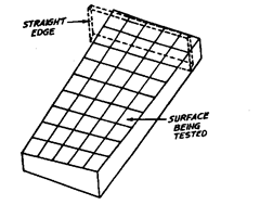
Fig. 2.26. Testing for flatness of a surface plate
using a straight edge.
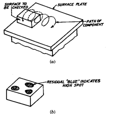
Fig. 2.27. Testing for flatness of surface plate.
The instrument is set so that its measuring probe registers zero or datum on a small central lapped
pad on the gauge. Leaving the zero set, the twist gauge is swung 90° to the opposite diagonal corners.
The relative difference in heights, or “twist” is registered as a plus-or-minus reading against
the lapped pad. It may be noted that even though the twist gauge sags appreciably, but this sag is
constant in both the positions.
(b) Using three-footed twist gauge. It is used to detect local errors. It has two gauging lapped
pads at the bottom corners of the single foot side. A small wedge shaped gauge having a slight taper
of approximately 1 ^m per 10 mm of length is pushed under the lapped flats (gauging pads) to
calibrate change in height of the lapped flats. This twist gauge is self-proved upon being turned 90°
on the surface plate and tested once again.
(c) Surface gauge with a protruding arm having electronic probe. This instrument is used to
search more local errors. It employs an electronic indicator, a stand and a small lapped block. If the
correct scraping procedure is followed then local errors will be minimum and errors may be of the
nature of overall bow or twist.
(d) Straddle surface gauge and a straight edge. It is used to determine overall “bow”. The
straight edge has two support feet 0.5547′ apart and three indicating pads on the straddle surface
gauge. The special straight edge is self-checked by reversal.
4. In testing the flatness of surface plate, it is the general practice to measure the actual
deviation from the true plane at various points. The method of testing a flat surface with sensitive
level or auto-collimator is described in detail in Chapter 7. Here we shall discuss the Beam
Comparator Method which is very quick method and very accurate one also. This method is
particularly convenient for testing the flatness of surface during manufacture.
This method is based on the principle of comparing the straightness of a succession of
generators in the surface under test with that of a known reference straight edge. The comparison
is carried out by the Beam Comparator, a sort of sensitive dial indicator which, in effect, measures
the vertical displacement of the midpoint of any particular generator with respect to a theoretical
straight line joining its ends. From these measurements, the idea of the apparent convexity or
concavity of generator can be had, which may be used to determine the general departures, of the
surface from mean true plane as explained later.
The body of the comparator consists of a robust but light beam having three supporting feet
made of hardened steel and spherically ended, one fixed at the centre of beam but offset from the

Fig. 2.28. Beam Comparator.
line joining the other two. The two supporting feet at the ends may be clamped to the beam in
symmetrically disposed positions with respect to the central foot and at a distance apart depending
upon the size of the surface under test. By having only three supporting feet, the beam is accidently
liable to be rolled over on the side not supported by the offset foot. In order to avoid this, a fourth
foot in the form of a spherically ended spring plunger is provided at a position symmetrically opposite
the fixed offset foot. The fourth foot is normally arranged to be reasonably clear of the surface plate
and comes into operation only if the beam tends to fall.
A very sensitive dial indicator supported in the central web of the beam and the axis of its
spherically ended contact plunger lies in the plane through the axis of the two adjustable feet.
For testing purposes a reference surface is employed whose straightness has already been
checked by other methods and thus the errors of its straightness are known. The comparator is
supported upon equal slip gauges or lapped pads on both the reference and the test surfaces so that
the feet of the beam comparator do not accidently locate in the hollows of the scraped surface, and
the readings are taken with respect to the high spots of the surface.
Method of Use. The method adopted for computing the results obtained from single generator
is illustrated more clearly by taking an example of testing a surface plate of size 100 mm x 60 mm.
Generally the flatness of the plate towards the edges is not bothered and thus a distance of about
5 cm from all the edges is not considered. The surface plate is marked as shown in Fig. 2.29 with a
lead pencil. For marking purposes, chalk should never be used which gets deposited in the hollows
of scraped portion and is harmful. The general and most commonly adopted practice of dividing the
plate is as shown in Fig. 2.29 according to which eight generators (AB, HF, DC; AD, EG, BC; AC,
BD) are tested. In addition, readings are also obtained for semi-diagonals of span AX, BX, CX and
DX.

Fig. 2.29. Scheme of test for a surface plate.
The span of the adjustable feet is set in turn for each of the different generators and
observations are taken first on the reference surface, then on the surface plate and finally on the
reference surface again.
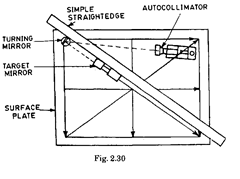
Fig. 2.30 shows another way for calibrating surface plate flatness in the same manner. This
method uses an autocollimator, reflecting target mirror.
In Table on next page for gener-
ator AC the total span between two ad-
justable feet was set as 103 cm (col. 2).
The first reading was taken on the refer-
ence surface which was 5.1. (col. 2, 1st
reading). Then reading was taken on the
test plate which was noted as 5.7
divisions (col. 6). The reading was again
taken on the reference surface and this
time also it was 5.1 divisions (col. 3, 2nd
reading). Thus the mean of 1st and 2nd
readings on the reference surface is 5.1
divisions. The known error at the central
region of the span on the reference sur-
face was known to be hollow by 0.0002
mm. i.e., equivalent to — 0.2 division on the indicator (col. 4), i.e. the indicator gave a reading of
0.0002 mm less than it would have done on a truly flat surface. Thus the indicator would be expected
to read 5.3 divisions (col. 5) on a truly flat surface. As the reading on test plate is 5.7 divisions (col.
6), the mid-point X on generator AC is convex by (5.7 – 5.3) divisions (i.e. 0.0004 mm) in reference
to the straight line joining points A and C.
The comparator is then turned until the end feet are stationed at B and D. In this case the
reading on the indicator obtained was 4.5 divisions (col. 6). It may be noted that for this span the
comparator has already been checked on the reference surface and thus the reading of reference
surface will be same as for AC. This time the pointZ is (4.5 – 5.3 = – 0.8 division) 0.8 division below
the straight line joining points B and D. It may be noted here that one setting and calibration of
the comparator span served for checking the centre point of both the diagonals of the plate.
Similarly only one setting and calibration is required for generators AB, HF, DC, one for AD,
EG, BC and one for semi-diagonals AX, BX, CX andDX. In the manner described above, the column
(7) can be determined for all the generators.
The next step is now to correlate the results. For this first of all the departure of various
points on the surface is derived from some arbitrary plane. For convenience, it is selected as that
passing through the points A, B and C of the source plate to which zero errors are accordingly
Observations and Calculations relating to the test of 100 cm x 60 cm surface plate
(Division of the indicator = 0.001 mm)
| 1 | 2 | 3 | 4 | 5 | 6 | 7 | 8 | 9 | |||
| Gener- | Central | Span | Reading on reference | Known | Corrected | Reading | Convexity | Basic | Results | ||
| ator | Point | (cm) | surface | error of | reference | on test | or concavity | reading | |||
| reference surface |
readings (3)-(4) |
plate | of Generator (6)-(5) |
at centre of span |
|||||||
| First reading |
Second reading |
Mean | |||||||||
| AC | X | 103 | 5.1 | 5.1 | 5.1 | -0.2 | 5.3 | 5.7 | + 0.4 | 0 | X + 0.4 |
| BD | X | 103 | 5.1 | 5.1 | 5.1 | -0.2 | 5.3 | 4.5 | -0.8 | — | D + 2.4 |
| AB | E | 90 | 4.7 | 4.7 | 4.7 | -0.3 | 5.0 | 5.2 | + 0.2 | + | E + 0.2 |
| HF | X | 90 | 4.7 | 4.7 | 4.7 | -0.3 | 5.0 | 4.8 | -0.2 | + 0.6 | (X + 0.4) |
| DC | G | 90 | 4.7 | 4.7 | 4.7 | -0.3 | 5.0 | 5.4 | + 0.4 | + 1.2 | G+ 1.6 |
| AD | H | 50 | 3.5 | 3.7 | 3.6 | + 0.1 | 3.5 | 3.7 | + 0.2 | -1.2 | H + 1.4 |
| EG | X | 50 | 3.5 | 3.7 | 3.6 | + 0.1 | 3.5 | 3.0 | -0.5 | + 0.9 | (X” + 0.4) |
| BC | F | 50 | 3.5 | 3.7 | 3.6 | + 0.1 | 3.5 | 3.3 | -0.2 | 0 | F-0.2 |
| AX | J | 51.5 | 5.4 | 5.4 | 5.4 | 0.0 | 5.4 | 5.6 | + 0.2 | + 0.2 | J-0.4 |
| BX | K | 51.5 | 5.4 | 5.4 | 5.4 | 0.0 | 5.4 | 5.5 | + 0.1 | + 0.2 | K + 0.3 |
| CX | L | 51.5 | 5.4 | 5.4 | 5.4 | 0.0 | 5.4 | 5.2 | -0.2 | -0.2 | L + 0.0 |
| DX | M | 51.5 | 5.4 | 5.4 | 5.4 | 0.0 | 5.4 | 5.0 | + 1.4 | + 1.4 | M + 1.0 |
assigned, i.e. these points are treated as zero. From the table, it will be observed that the generator
AC is convex by 0.0004 mm. As points A and C are treated as zero, the point X should be assigned
a value of + 0.0004 or 0.4 division. The next step now is to assign a value to D. From the observations
it is noted that generator BD is concave by 0.0008 mm. i.e., point X is 0.8 divisions below the line
joining points B and D. But it has already been seen in the generator AC, that point X with respect
to datum plane ABC is 0.4 division above it. Since point X is common to both the diagonals, it is,
therefore, necessary to adjust the direction of the generator BD about its end-point B until the
mid-point X coincides with the assigned value of X at + 0.4 division. To do this, the mid-point X
should be raised by 1.2 divisions and thus point D by 2.4 divisions. It is thus observed that for
generator AC, the value of mid-pointX remains same as + 0.4 because points A and C were assumed
to be zero and, therefore, there was no basic reading at centre of span. Therefore, in column (8) for
generator AC, value is put zero and the final result (col. 9) is that pointX which is 0.4 division above
datum plane ABC and it is put as X + 0.4. For generator BD, the method for finding the height of
point D above the datum plane ABC has already been described above and the generalised formula
does not hold for it and, therefore, entry in col. (8) is (-) and final result is that pointD is 2.4 divisions
above datum plane and thus entry in col. (9) is D + 2.4.
To obtain the values for E, F, G and H the following reasoning is applied. As the values
assigned to A, B and C are zero, the values of E and F would also be zero if generators AB and BC
were straight. Thus for generators AB and BC, the basic reading at centre of span is zero (col. 8)
and the values of their mid-points E and F will be 0.2 division and – 0.2 division respectively from
datum plane as obtained from col. 7. In col. 9 the entries for generators AB and BC would thus be
E + 0.2 and F – 0.2. Similarly, as D is + 2.4 divisions and A and C are zero, then if generator AD
and DC were straight, the values of H and G would be + 1.2 divisions (see col. 8 for generators AD
and DC). It is helpful to note that the ‘basic’ value for the mid-point of any span is the mean of
values already assigned to the end-points. Now as the mid-pointH of generator AD is already convex
by 0.2 division, then with reference to datum plane AB, it will be convex to 0.2 + 1.2 divisions, i.e.
1.4 divisions and thus entry in col. 9 against generator AD is H + 1.4. Thus col. 9 is algebraic sum
of col. 7 and 8. In this way cols. 8 and 9 for all the generators can be computed.
The basic values forX” and-X” (col. 8) are obtained by making use of the results given in col.
9 for E, F, G and H. The results in col. 9 for X and X” are obtained by combining col. 7 with col. 8.
It may be noted that X and X” are positions coincident with X but derived from spans HF and
EG: whereasX was derived from span AC. The values ofX’, X’ should be same as of X and, therefore,
it acts as a convenient check on the accuracy of observations.
Now the results of col. 9 are easily
comprehend as shown in Fig. 2.31, i.e. the
location of all points w.r.t. the datum plane
ABC is marked on the points themselves.
It may be noted that the datum plane
ABC was chosen quite arbitrarily and need not
necessarily be the mean true plane. Mean true
plane is actually such a plane which lies nearly
in between the various points on the surface,
i.e. exact location of various points is uniform-
ly distributed on either side of the mean true
plane and the various points are at minimum
distance from it.
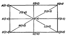
Fig. 2.31. Measurement errors referred to an arbitrary
datum plane through the points A = B = C = 0.
For determining such a plane, a visual inspection of the results plotted in Fig. 2.31 is usually
sufficient e.g. in this case it will be noted that
the surface lines within two planes [+ 2.4 and
(0.2)] 2.6 divisions or 0.0026 mm apart. It will
be observed that point D is most troublesome
and is responsible for very much displacing
apart the two planes under which all points
lie. If the plane ABC be rotated about the line
AC by an amount corresponding to 1.2
divisions atD andB, then the values of various
points will be as shown in Fig. 2.32 and it
seems to be mean true plane, of course, the
exact mean true plane may never be deter-
mined and some error will always be there.
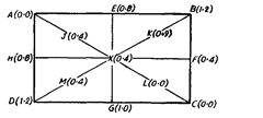
Fig. 2.32. Results referred to a datum plane selected
to give best distribution of errors.
It is apparent from Fig. 2.32, that the surface lies within two planes separated by a distance
of 0.0012 mm or the surface lies within ± 0.0006 mm from a mean true plane. (Please also refer Art.
7.2).
The working surface of surface plates can be explored with the variation gauge. The variation
gauge (Refer Fig. 2.33) consists of a freely moving base with three co-planer pads for bearing on the
surface being tested. It carries an indicator to indicate variations in deviation from flatness from
adjacent areas of that surface through a fourth co-planer pad, which is itself mounted on an
intermediate sprung block.

Fig. 2.33. Variation gauge.
2.5.9.
Testing by comparison with a liquid surface.
This method utilises the surface of
a liquid as a basis of reference and is probably the most rapid method and can be conveniently
applied to quite large surfaces with an accuracy of the order of 0.005 mm. The liquid is a weak soda
solution which is contained in a trough made from a length of angle or channel iron and supported
over the surface to be tested. In this method a special type of surface gauge is used to compare the
flatness of the surface of the work with that of the liquid.
The instrument consists of a substantial base provided with a stiff column which carries a
bracket holding a micrometer head in an overhanging vertical position with the spindle pointing
downwards and acting like a height gauge. The gauge rests on the work with its base beneath the
trough and the micrometer head over the liquid surface. The reading is noted down by screwing
down the micrometer head until the conical tip of the spindle (having radius of about 0.5 mm) just
makes contact with the liquid. This may be indicated electrically be connecting a dry cell and a
galvanometer in series with the trough and the work. Care has to be taken to keep the tip of spindle
perfectly dry.
This test is carried out by first levelling the surface such that the two readings obtained with
the surface gauge in its extreme positions are the same. Readings are then taken with the gauge
at intermediate points and any variation in these readings from those obtained in the end positions
indicate errors in the work surface along the region beneath the trough. For large surfaces a number
of troughs are set up parallel to each other and connected together at one end with rubber tubing
so that their liquid surfaces are at the same level.
In a simple test shown in Fig. 2.34, two gauges are connected together by a stout rubber
tubing. After setting the surface to be tested perfectly horizontal, one gauge is placed in the centre
and the other gauge is moved from one place to other on the surface and for each position a reading
is taken on each of the two micrometer heads. Difference in two readings as the other gauge is

Fig. 2.34
moved from place to place indicates the errors in flatness at position tested. If the surface as a whole
has not been set quite horizontal this will be indicated by the readings and be allowed for when
plotting the results so as to give a diagram showing the errors in flatness of the surface from its
mean true plane. The precaution to be observed is that interconnecting tubing must be free from
air bubbles. In order to avoid the surging of liquid from one cup to another and for attaining better
equilibrium, a stop cock may be provided in the tube which is shut while moving the second cup
from one position to another. The work should be avoided from the effects of vibration which causes
ripples on the surface of liquid.
2.5.10.
Care and use of surface plates
1. The surface plate is a datum and needs to be protected against damage. When not in use,
it should always be kept covered. During use, top should be frequently wiped clean from dust and
other particles. When measurements are being made, a wiping cloth should be spread on the surface
plate to receive small tools and gauge blocks.
2. Surface plate should be located in a stirred atmosphere under constant temperature
control. Direct sunlight or sudden draughts should not be allowed to reach surface plate. Vertical
gradient of temperature subjecting the top and underside of surface plate to different temperatures
should be avoided.
3. The surface plate should be supported firmly and levelled. Stands should be located on a
stable foundation.
4. The load on the surface plate should be distributed over the working surface, as far as
possible.
5. Point engagement should not be made with scraped or machined surface plates. To avoid
direct point engagement with the surface plate, contact should be made through an intermediate
precision gauge block or a distance piece, preferably, not more than 10 mm tall.
6. Use should be made of the full available area of the working surface and not concentrated
on any one area.
The variations in local flatness of the surface should be checked occasionally by using a
variation gauge.
7. The excess metal due to burrs on the working surface of cast iron surface plate should be
stoned away by confining attention to the burr. This operation should be followed by thorough
cleaning from abrasive dust. If the surface plate is not required for some days, the surface should
be coated with a corrosion preventive such as petroleum jelly.
8. Rusting can be reduced by frequently wiping the top when in use and by occasionally
gently rubbing with another surface plate using a paste of paraffin and a little jeweller’s rouge as
a lubricant.
9. The wear on surface plate can be detected by rubbing it with a superior grade of surface
plate and studying the rubbed appearance, by testing for deviation from straightness along lines
on the surface plate, and/or using a variation gauge.
