8.6.
The sine principle uses the ratio of the length of two sides of a right triangle in deriving
a given angle. It may, be noted that devices operating on sine principle are capable of “self
generation”. The measurement is usually limited to 45° from loss of accuracy point of view.
The accuracy with which the sine principle can be put to use is dependent in practice, on some
form of linear measurement. The sine bar in itself is not a complete measuring instrument.
Another datum such as a surface plate is needed, as well as other auxiliary equipment, notably
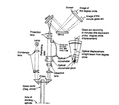
Fig. 8.9. Diagrammatic arrangement of the optical system employed in optical dividing head.
slip gauges, and indicating device to make measurements. Sine bars used in conjunction with
slip gauges constitute a very good device for the precise measurement of angles. Sine bars are
used either to measure angles very accurately or for locating any work to a given angle within
very close limits. Sine bars are made from high carbon, high chromium, corrosion resistant
steel, hardened, ground and stabilised. Two cylinders of equal diameter are attached at the
ends. The axes of these two cylinders are mutually parallel to each other and also parallel to
and at equal distance from the upper surface of the sine bar. The distance between the axes
of the two cylinders is exactly 5 inches or 10 inches in British system, and 100, 200 and 300
mm in metric system. The above requirements are met and maintained by taking due care in

Fig. 8.10. Sine bar.
the manufacture of all parts. The various parts are hardened and stabilised before grinding
and lapping. All the working surfaces and the cylindrical surfaces of the rollers are finished to
surface finish of 0.2 [im Ra value or better. Depending upon the accuracy of the centre distance,
sine bars are graded as of A grade or B grade. B grade of sine bars are guaranteed accurate
upto 0.02 mm/m of length and A grade sine bars are more accurate and guaranteed upto 0.01
mm/m of length.
Although there are several forms of sine bars, but the one shown in Fig. 8.10 is most
commonly used. Some holes are drilled in the body of the bar to reduce the weight and to
facilitate handling.
However, from the point of view of ease in manufacturing to ensure an exact distance
between the cylinders, the form shown in Fig. 8.11 is preferable. Also this type of sine bar can
be set to a steep angle without the slip gauges fouling the underside of the bar. But this point
is immaterial as the accuracy of setting appreciably decreases with steep angles and from the
point of stability also we generally do not use sine bars for steep angles.
Before using any sine bar for angular measurement work, for accuracy and precision,
it is better to ensure whether the following accuracy requirements and tolerances as specified
by I.S. 5359—1969 for 100 mm sine bar are met with :
Characteristics Permissible Tolerance
Flatness of upper and lower surfaces 0.001 mm
Parallelism of upper and lower surfaces w.r.t. datum
surface when resting on it 0.001 mm
Flatness of side faces 0.005 mm
Squareness of side faces to upper surface 0.003/25 mm
Parallelism of side faces to the axes of rollers 0.01/25 mm
Flatness of end faces 0.003 mm
Squareness of end faces to the upper surface 0.003/25 mm
Parallelism of end faces to the axes of the rollers 0.01/25 mm
Straightness of individual rollers and freedom from lobing and
uniformity in diameter 0.002 mm
Mean diameter of rollers 0.002 mm
Distance between the roller axes ± 0.003 mm
Roller axes:
(i) In a common plane over the length of either roller 0.003 mm
(ii) Parallel to and equidistant from the upper surface over the
length of either roller 0.003 mm
Flatness of the bearing surface of the setting foot 0.003 mm
Various types i.e., different designs of sine bars required for different applications are
shown in Fig. 8.10. Fig. 8.11 also shows the nomenclature of sine bars as recommended by
IS : 5359—1969.
As already pointed, sine bar shown in Figs. 8.10 to 8.14 is more preferred form as the
distance between the rollers in this case can be adjusted exactly.
This type of sine bar can be easily set on steep angle without the slip gauges fouling the
underside of the sine bar ; of course, the accuracy of setting decreases with steep angles.
Sine bar shown in Fig. 8.12 is most commonly used form in which the rollers are so
arranged that their outer surfaces on one side are level with the plane top surface of the sine bar.
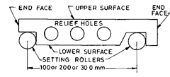
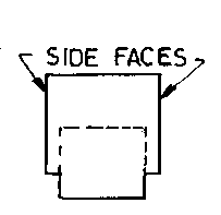
Fig. 8.11

Fig. 8.12

Fig. 8.13

Fig. 8.14
Different types of sine bars.
The form of sine bar shown in Fig. 8.13 has hollow rollers whose outside diameter is
equal to width of sine bar and is used where the width of the sine bar enters into calculation
of work height.
The form of sine bar shown in Fig. 8.14 is used where ordinary type can’t be used on the
top surface due to interruption.
The accuracy of sine bar depends on its constructional features and on maintaining
these.
These features are :
(i) The two rollers must have equal diameter and be true cylinders.
(ii) The rollers must be set parallel to each other and to the upper face.
(iii) The precise centre distance between the rollers must be known.
(iv) The upper face must have a high degree of flatness. The various characteristic
tolerances have already been indicated above.
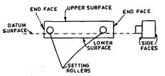
Fig. 8.15 shows the various types of sine bars as recommended by BS : 3064.
The accuracy requirements for sine as specified by British standard BS : 3064 are
(i) Flatness of whole of the upper surface of bar (and also of lower surface if it is working
surface): 0.0015, 0.002 and 0.003 mm respectively for 100, 200 and 300 mm bars.
(ii) Parallelism of lower
and upper surfaces—Same
tolerances as for (£) above.
(iii) Flatness of side faces of
bars : 0.004, 0.005 and 0.006 mm
for 100, 200 and 300 mm bars
respectively.
(iv) Squareness of the side
faces to the upper surface of bar :
0.0025 mm per 25 mm.
Type 1
(v) Squareness of the side
faces to the axis of the hinge
roller : 0.013 mm per 25 mm.
(yi) Flatness of end faces (if
to be used as working surfaces):
within 0.0025 mm.
(vii) Squareness of end
faces (if to be used as working
surfaces) to the upper surface of
the bar : within 0.0025 mm per
25 mm.
(viii) Parallelism of end
faces to the axis of the hinge
roller : within 0.013 mm per
25 mm.
(ix) Uniformity of radius
and straightness over length of
setting and hinge rollers : within
0.002 mm.
(x) Equal sizes of setting
and hinge rollers—to be within
0.0025 mm.
(xi) Accuracy of distance
between roller axes : 0.0025,
0.005 mm, 0.008 mm for 100,200
and 300 mm bars.
(xii) Additional require-
ment of rollers. The roller axes
should lie in a common plane
within 0.002 mm over the length
of either roller. Further the upper
surface and lower surface (if
working surface) should be
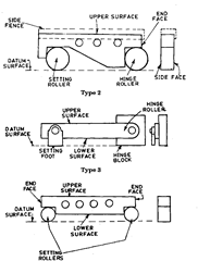
Type 4
Fig. 8.15. Types of sine bars as per BS : 3064.
parallel to the plane tangent to the lower surface of the rollers within 0.002 mm.
(xiii) Flatness of end and side faces—within 0.005 mm.
8.6.1.
Use of Sine Bar.
(1) Measuring known angles or locating any work to a given
angle. For this purpose the surface plate is assumed to be having a perfectly flat surface, so
that its surface could be treated as horizontal. One of the cylinders or rollers of sine bar is
placed on the surface plate and other
roller is placed on the slip gauges of
height h. Let the sine bar be set at an
angle 9. Then sin 8 = h/l, where I is the
distance between the center of the
rollers. Thus knowing y, h can be found
out and any work could be set at this
angle as the top face of sine bar is
inclined at angle 6 to the surface plate.
The use of angle plates and clamps

Fig. 8.16. Use of sine bar.
could also be made in case of heavy components. For better results, both the rollers could also
be placed on slip gauges of height hx and h2 respectively. Then sin 0 = (h2 – h{)ll.
(2) Checking of unknown
angles. Many a times, angle of a com-
ponent to be checked is unknown. In
such a case, it is necessary to first find
the angle approximately with the help
of a bevel protractor. Let the angle be
8. Then the sine bar is set at an angle
6 and clamped to an angle plate. Next,
the work is placed on sine bar and
clamped to angle plate as shown in Fig.
8.17 and a dial indicator is set at one
end of the work and moved to the
other, and deviation is noted. Again
slip gauges are so adjusted (according
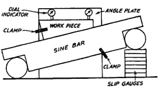
Fig. 8.17. Checking unknown angle using sine bar.
to this deviation) that dial indicator reads zero across work surface.
If deviation noted down by the dial indicator is bh over a length V of work, then height
of slip gauges by which it should be adjusted in equal to = hh x HI’.
(3) Checking of unknown angles of heavy component. In such cases where components
are heavy and can’t be mounted on the sine bar, then sine bar is mounted on the component
as shown in Fig. 8.18. The height
over the rollers can then be
measured by a vernier height
gauge ; using a dial test gauge
mounted on the anvil of height
gauge as the fiducial indicator to
ensure constant measuring pres-
sure. The anvil on height gauge is
adjusted with probe of dial test
gauge showing same reading for the
topmost position of rollers of sine
bar. Fig. 8.18 shows the use of
height gauge for obtaining two read-
ings for either of the roller of sine
bar. The difference of the two read-
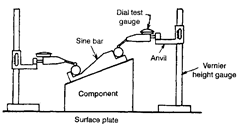
Fig. 8.18. Checking unknown angle of heavy component
using sine bar.
ings of height gauge divided by the centre distance of sine bar gives the sine of the angle of the
component to be measured. Where greater accuracy is required, the position of dial test gauge
probe can be sensed by adjusting a pile of slip gauges till dial indicator indicates same reading
over roller of sine bar and the slip gauges.
8.6.2.
Limitations of Sine Bars.
The establishment of angle by the sine principle is
essentially a length measuring process. Thus the accuracy, in practice, is limited by measure-
ment of centre distance of two precision rollers. The geometrical condition involved in
measuring the exact, effective centre distance existing between two rollers of the sine bar to a
certainty of fraction of a um is an infinitely complex problem. This fundamental limitation
alone precludes the use of the sine bar as a primary standard of angle.
Devices operating on the sine principle are fairly reliable at angles less than 15°, but
become increasingly inaccurate as the angle increases.
Sine bars inherently become increasingly impractical and inaccurate as the angle
exceeds 45°.
The sine bars inherently become increasingly impractical and inaccurate as the angle
exceeds 45° because of following reasons :
— The sine bar is physically clumsy to hold in position.
— The body of the sine bar obstructs the gauge block stack, even if relieved.
— Slight errors of the sine bar cause large angular errors.
— Long gauge stacks are not nearly as accurate as shorter gauge blocks.
— Temperature variation becomes more critical.
— A difference in deformation occurs at the point of roller contact to the support surface
and to the gauge blocks, because at higher angles, the weight load is shifted more
toward the fulcrum roller.
— The size of gauges, instruments or parts that a sine bar can inspect is limited, since
it is not designed to support large or heavy objects.
8.6.3.
Precautions in use of sine bars.
(i) The sine bar should not be used for angle
greater than 60° because any possible error in construction is accentuated at this limit. (Also
refer Prob. 8.2).
(ii) A compound angle should not be formed by mis-aligning of workpiece with the sine
bar. This can be avoided by attaching the sine bar and work against an angle plate.
(iii) Accuracy of sine bar should be ensured.
(iv) As far as possible longer sine bar should be used since many errors are reduced by
using longer sine bars.
8.6.4.
Sine Table.
This is the development of the sine bar and the procedure of setting
it at any angle is same as for sine bars. The sine table is the most convenient and accurate
design for heavy workpiece. The table is quite rugged one and the weight of unit and workpiece
is given fuller and safer support. The gauging platforms are self-contained and can be highly
refined. The table may be safely swung to any angle from 0° to 90° by pivoting it about its
hinged end. Two sets of sturdy non-influencing clamps are provided for supporting the table
on both sides over the whole range of sine table. It may be noted that the table is a long level
which bends and twists when put through various angles while supporting all sorts of shapes,
sizes and weights of workpieces. The clamping mechanism of the sine table may also cause
distortion, varying the angle set slightly. However the errors due to these are not generally
large.
The sine table is capable of exceptional accuracy if user uses it properly, construction
principles and all elements of sine table are correct, the gauge block stack is correct and at
same temperature as sine table. The sine table should be elevated or lowered, using the fine
adjustment feature to attain the desired “feel” between the gauge blocks and pins of both sides
separately.
A further development of this is the compound sine table in which two sine tables having
their axes of tilt set at right angles to each other are provided. These two tables are mounted
on a common base and the table can be set at compound angle by resolving this compound
angle into its individual angles in two planes at right angles to each other and setting each
table accordingly.
The “double sine” principle employs gauge pins rather than gauging platform in both
table and base of the sine table. This design allows angular settings to a full 90°, and minimises
the errors normally inherent in a sine table at greater angles.
8.6.5.
Sine Centre.
Sine centre is basically a sine bar with
block holding centres which can be
adjusted and rigidly clamped in any
position. These are used for inspec-
tion of conical objects (having male
and female centres.) between
centres. These are used upto in-
clination of 60°. Rollers are clamped
firmly to the body without any play.
This is a very useful device for test-
ing the conical work centered at
each end. The principle of setting is
same as of sine table.
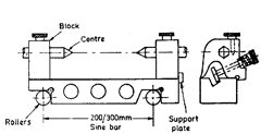
Fig. 8.19. Sine Centre.
