2.27.
As modern production is concerned with inter-
changeable products, a great precision dimensional
control is required in industry. For this to be achieved,
importance of precision measuring instruments can be
well visualised.
2.27.1.
Characteristics of Precision Measuring Instruments.
In order that precision
measuring instruments function properly, they should possess the following characteristics :
(a) high degree of sensitivity (b) high degree of accuracy and (c) minimum inertia in the moving
parts of mechanism. Sensitivity of the instrument may be defined as the rate of displacement of the
indicating device with respect to the quantity to be measured. Literally, sensitivity is defined with
reference to the least change in the measured quantity which will cause an observable change in
the instrument reading. In instrument design an attempt must be made that sensitivity remains
constant throughout the range of measured quantity. The measure of accuracy of an instrument
can be had by the amount of correction to be made to the instrument reading. The accuracy will be
high, if calibration is proper and less wearing of parts takes place. The effect of inertia of moving
parts is to make the instrument sluggish. All those instruments which depend on linkage and
mechanical system, displacement of fluid, diaphragm etc. are subjected to disadvantages of inertia.
Thus imperfect elasticity of the diaphragms and spring are causes of inertia in instruments.
However instruments based on the principle of optics are entirely free from inertia effects.
In addition to these three characteristics, the measuring instruments must have freedom
from variance. Variance is defined as the range of variance in instrument readings obtained from
repeated measurements of same quantity. It is inherent in the instrument and depends upon the

Fig. 2.84. Pitch screw gauge.
quality of instrument which in turn depends upon the quality of machines from which it is
manufactured and quality of workmanship.
In order to achieve the above mentioned characteristics in the measuring instruments, the
following principles must be observed.
2.27.2.
Principle of Alignment.
According to it the line of measurement (axis of scale)
should be coincident with the line of the dimension being measured (the axis of the specimen whose
dimension is being measured). The principle is known as Abbe principle of alignment. Abbe principle
also states that if it is not possible to have the displacement measuring system in line with the
functional point whose displacement is to be measured then either the slide-ways that transfer the
displacement must be free of angular motion or angular motion data must be used to calculate the
consequences of the offset. Abbe principle is followed in the case of micro-meter screw gauge. But
in case of vernier caliper this is not followed. Therefore, there is possibility of error in vernier caliper.
In vernier caliper, the specimen (whose dimension is to be measured) is placed between two jaws
and the axis of this is quite far away from the axis of scale. Now let us say that due to force of
tightening a slight curvature is brought in the vernier beam (scale), then obviously due to curvature
of scale, it will not show the same reading as that of specimen since tightening pressure will vary
from person to person; reading obtained by different persons will be different. Hence generally the
principle of alignment should be followed in the design of measuring instruments, as far as possible.
(Also refer solved problem at the end of the chapter).
2.27.3.
Principle of Kinematics.
Here we are concerned with the theory of location and
movement. Any rigid body in space can have six degrees of freedom of movement. These movements
are linear along the three axes in space and three movements are rotational about the three axes.
Thus in order to completely constrain a body from all movements, all the six degrees of freedom
must be checked. For having one degree of freedom of movement, five degree of freedom must be
constrained. Thus theoretically for a better design, the component parts should not have redundant
locations or restraints.
The various ways to apply these constraints are conical holes, vee-grooves and flat surfaces.
By conical hole the three linear movements are constrained. With V-groove two linear movements
and two rotational movements are constrained while with a flat surface one linear movement and
one angular movement is constrained. Using the proper combinations of these three methods, any
degree of freedoms can be constrained.
Theoretically, the contact between the component parts of a kinematic design should take
place at single point. But in that case they can’t withstand much of impact, and robustness of the
instrument is sacrificed. Hence these must be used very carefully. However to provide the necessary
robustness kinematic principles can be modified slightly.
2.27.4.
Measuring Contacts.
Measuring faces are
generally either flat or spherical at the position of contact.
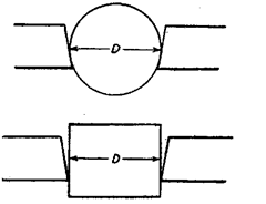
In case of flat contacts, faces must be flat and parallel
to each other. If not so then errors will be introduced in the
measurement of a ball and flat piece of same size (Fig. 2.85).
(Also refer solved problem at the end of the chapter).
Secondly the work must be free to align itself relative to the
measuring faces and normal operation of measurement
should not upset the parallelism of the measuring faces. For
flat pieces one measuring face must be spherical one and ,
other flat one, while in case of circular specimen, both faces
must be flat.

Fig. 2.85. Here the width D of rect-
angular block will appear larger
than diameter D of the ball.
2.27.5. Selection of measuring instrument. Discrimination is a major factor in the
selection of proper measuring instrument. One should consider the variable to be measured and
the discrimination of the measuring device desired. Other points to be considered are the level of
sensitivity or resolution that can be expected; the accuracy and precision required of the measuring
device and the conditions required to use this device properly.
Dealing with above factors successfully is important. It should be analysed as to what
measuring devices, techniques and sequences would be most successful in optimising the inspection
or measurement. How should the results be reported or displayed is also important consideration.
Lastly it should be ensured that what inspection system guarantees that this same meas-
urement technique will yield comparable or repeatable results next time.
It must be remembered that the measuring devices possessed of a large measuring range
offer a trade off in terms of discrimination. For instance, mechanical and electronic instruments
having great amplification (and thus more discrete scales of discrimination), have less range.
Every instrument possesses some inherent amount of error or uncertainty, expressed as
accuracy of the instrument. In assessing the performance of a measuring instrument, the perfor-
mance expectations of the instrument must first be considered in terms of accuracy. Obviously, the
choice of the proper measuring instrument for an inspection is based on a prior expectation of its
accuracy. On the other hand precision of instrument refers to repeatability.
The number of graduations on an instrument or the degree to which it subdivides one
centimeter is known as discrimination. Estimation of exact reading between two smallest gradua-
tions should not be attempted. If requirement is to measure exactly between two smallest divisions,
then apparatus with fine discrimination (line vernier calipers or micrometer screw gauge) should
be used.
