5.8.
Air gauging has rapidly increased during some past time due to the following important
characteristics:
(a) Very high amplifications are possible. It can be used to measure diameters, length,
squareness, parallelism, concentricity, taper, centre distance between holes and other
geometric conditions.
(b) As no physical contact is made either with the setting gauge or the part being
measured, there is no loss of accuracy because of gauge wear. For this reason, air spindle and
air snap gauges last very long. Also very soft parts which are easily scratched, can be gauged.
(c) Internal dimensions can be readily measured not only with respect to tolerance
boundaries but also geometric form. In other words, while measuring a bore it can reveal
complete story of size, taper, straightness, camber and bell mouth etc.
(d) It is independent of operator skill.
(e) High pressure air gauging can be done with cleansing of the parts which helps to
eliminate errors due to dirt and foreign matter.
(f) Gauging pressures can be kept sufficiently low to prevent part deflection.
(In general, high pressure gauges are suitable for those parts in which tolerances are
relatively large and low pressure air gauges are preferable for highly precise work.)
(g) Dimensional variations throughout the length of shaft or cylinder bore can be
explored for out of roundness, taperness, concertricity, regularity and similar conditions.
(h) Not only it measures the actual size, but it can also be used to salvage oversized
pieces for rework or to sort out for selective assembly, i.e., it is suitable both for variable
inspection (measurement of size) and attribute inspection (GO and NO GO) gauging and limits.
(i) The total life cost of the gauging heads in much less.
(j’) It is accurate, flexible, reliable, universal and speedy device for inspecting parts in
mass production.
(k) It is best suited for checking multiple dimensions and conditions on a part simul-
taneously in least possible time. It can be used for parts from 0.5 mm to 900 mm diameter
having tolerance of 0.05 mm or less. It can be easily used for on line measurement of parts as
they are being machined and take corrective actions.
5.8.1.
Systems of Pneumatic Gauges
. Based on the physical phenomena on which
the operation of pneumatic gauges is based, these may be classified as :
(i) Flow or velocity type, (ii) Back pressure type.
Flow or velocity type pneumatic gauges operate by sensing and indicating the momen-
tary rate of air flow. Flow could be sensed by a glass tube with tapered bore, mounted over a
graduated scale. Inside the bore a float is lifted by the air flow.
Velocity of air in velocity type pneumatic gauges can also be sensed by sensing the
velocity differential i.e., differential pressure across a venturi chamber. Such systems have

Fig. 5.32. Free flow air gauge.
quick response. These permit use of large clearance between nozzle and object surface,
resulting in reduced wear of the gauging members. There is less air consumption. Magnifica-
tion of the order of 500 to 5000 times is possible.
5.8.1.1.
Free Flow Air Gauges (Flow or velocity type).
In this case the compressed air
after the filtering and pressure reducing unit flows through a tapered glass tube containing a
small metal float and then through a plastic tube to the gauge head having two diametrically
opposed orifices for air escapement into atmosphere (Refer Fig. 5.32). The position of the tube
is dependent upon the amount of air flowing through the gauge head, which in turn is
dependent upon the clearance between the bore to be measured and the gauge head. Fig. 5.34
shows a curve between the air flow and the clearance between the part and the orifice in gauge
head.
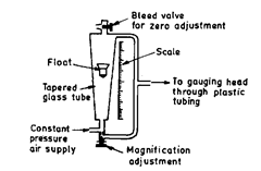
Fig. 5.33. Zero and magnification adjustment
in flow type pneumatic comparator.
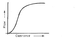
Fig. 5.34. Characteristic of air flow
versus clearance of flow.
The flow velocity type pneumatic comparator with zero adjustment and magnification
adjustment is shown in Fig. 5.33. Magnification can be changed by passing some of the air
supply, using a screw at the inlet to the tapered glass tube. The float can be zeroed by a bleed
valve installed at the top of the tube. Size is measured by the velocity of air in a tapered glass
tube which is measured by the height of the float in tube.
The straight portion of the curve is utilized for the measuring range. It provides high
amplification (10 : 1) and thus within the linear range, it is possible to read accurately upto
microns depending upon scale length, or classify the sizes quickly and accurately. The
amplification can be changed by quick change of tube, float and scale. Air gauge amplification
and range are based on the tooling and instrument standards of manufacturer. The amplifica-
tion and instrument are selected by considering the total tolerance spread and choosing the
instrument that covers the range. About 50 to 100 mm of column is usually allowed for the
actual tolerance spread.
In the gauging head, the air escapement orifices are recessed below its cylindrical
surface so that the orifices never contact the part being gauged. Thus the surface wear will not
affect the accuracy till it is worn down to orifice level. Also the orientation of gauge or the way
operator holds the gauge is of no consequence and same readings will be obtained for given
diameter. On the gauge, knobs are also provided for adjusting float position and calibration.
Air gauge is set by placing masters for maximum and minimum tolerances on spindle
alternatively and adjusting the float position for each master by turning the knurled knobs at
the base of the instrument.
Free-flow column type gauges are usually assembled together side by side and thus
multiple interrelated readings can be seen at a glance. This is the big advantage of air gauging
that the multiple dimensions and conditions can be inspected with great ease, accuracy and
speed.
Pneumatic circuits can be arranged to determine dimensional differences like taper
(comprising the diameter of bore at different points along a part), bore centre distance and also
to select parts to assemble to predetermined clearances or interference fits.
5.8.1.2.
Back Pressure Gauges.
The basic principle and the theory of pneumatic
gauging in the back pressure gauges is described below. (Refer Fig. 5.35)
Air from a constant pressure source
flows to the atmosphere through two orifices
Oc and Om in series.
P is the pressure upstream of the first
orifice andp is the pressure between the two
orifices, both measured with reference to
the atmospheric pressure as datum.

Fig. 5.35. Theory of pneumatic gauging.
The relationship between p and P will depend upon the relative sizes of the two orifices :
p being equal to P when Om is blocked and tends to zero as Om is increased indefinitely. Let C
be the geometrical area of Oe and M that of Om.
Then if p and C are kept constant while M is varied, the relationship between the
dimensionless quantitiesp/P and MIC is of the type shown in Fig. 5.36.
(The general form of this curve is quite well predicted by an analysis employing
Bernouli’s equation for flow of a compressible fluid.)
We are interested in linear portion of this curve.
For design purposes we follow an empirical approach which is based on an experimental
study at N.P.L. (London) of the relationship between pressures and orifices areas.
The characteristics of p/P and MIC are determined experimentally for pressure P
varying from 2 to 75 pounds per sq. inch (0.13 to 5 kg/cm2) and inspection of any one of these
shows that within the range 0.6p/P to 0.8p/P, the curve approximates to a straight line, the
equation for which mav be written as
![]()
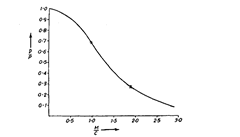
Fig. 5.36. Characteristic curve of pneumatic gauge.
Examination of the family of curves shows that constant A, the intercept on the p/P axis is
closely constant over the range of pressures investigated and for practical purposes, the value
of A = 1.10 can be adopted for any value of P likely to be used.
The slobe b of straight portion characteristics is however not independent of P, its
numerical value decreases as P increases and the limiting values found in the investigation
are as under :
b = 0.6 when P = 0.13 kg/cm2
b = 0.4 when P = 5 kg/cm2.
5.8.1.3.
Area of escape orifice.
When
the clearance between the surface and the
nozzle face is zero, no air escapes from the
nozzle and the area of the escape orifice is zero.
When the clearance between the sur-
face and the nozzle face is very large, the area
of the escape orifice is ^ d2, where d is the
diameter of the nozzle.
Between these extremes, especially
where the clearance is small and where air
gauging can be employed, the area of the
escape orifice is n dl, that is, the area of the
curved surface of the cylinder shown in
Fig. 5.38.
5.8.1.4.
Range of linear measurement.
The condition 0.6 < p/P < 0.8 defines a
section of the characteristics which ex-
perimental investigation has shown to be
linear to within 1%.
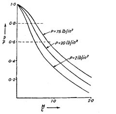
Fig. 5.37. Experimentally determined
characteristics for different operating pressures.

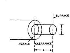
Fig. 5.38. Area of the escape orifice.

Fig. 5.39. Range of linear measurement.
5.8.1.5. Pneumatic Sensitivity, i.e. how p varies by variation of M.

5.8.1.6.
Changing sensitivity (Magnification).
A plot of pressure against escape
orifice area for a number of different sizes of control orifice will show that sensitivity increases
as the diameter of the control orifice decreases, i.e., for small control orifices the change in
pressure is greater for a given change in escape orifice area. Utilising this property, it is
possible to set precisely the sensitivity (magnification) by incorporating a variable control
orifice.
5.8.1.7.
Overall Magnification.
In a practical pneumatic measuring apparatus the
area M will be associated with the measuring head and change in M will be the result of a
change in the dimension which is
being measured e.g. a change in the
separation L between nozzle and
surface (Fig. 5.40).
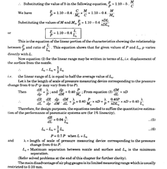
The overall magnification of
the apparatus, i.e. the ratio of the
linear movement of the pointer or
index of the pressure measuring in-
strument to the change in the

Fig. 5.40. Variation of M w.r.t. L.
![]()

This condition requires the measuring head to be correctly designed. The final escape-
ment of the air from the nozzle to the atmosphere is taken as being through an area of the
curved surface of the cylinder of length L and diameter D, where L is the separation between
the nozzle surface and the surface to be gauged and D is the internal diameter of the nozzle.

5.8.1.8.
Response Speed.
For a back pressure system the speed of response is not as
fast as for free-flow type, because some time is required for the pressure to build up. The speed
of response becomes of concern when the gauginghead is separated from indicating instrument
by long distance.
A pneumatic measuring system will not correctly measure displacements of frequency
greater than about 2 cycles/second, because of its slow speed of response. The response is
considerably slower compared to the electrical system because of the following reasons.
Between the control orifice and the measuring head, there exists a closed volume associated
with the measuring instrument used to measure the pressure p. A dimensional change, e.g., a
displacement of the surface alters the flow so changing the pressure p. The time needed to
establish the new value of p depends on the total volume and on the rate of air flow into and
out of it. The latter in turn depends upon the operating pressure P and the size of the control
orifice and orifice in the measuring head. These orifices are related in size and determine the
pneumatic sensitivity, the smaller orifices (corresponding to the higher magnification), having
a more restrictive effect on the air flow and so slowing the response.
It has been examined theoretically and experimentally that response is slowed by using
a large operating pressure P and a large volume, but by these high sensitivity (magnification)
is obtained. In any practical pneumatic measuring system, the overall response will be
influenced by dynamic characteristics of the pressure measuring device. Thus it follows that
the use of a low operating pressure will not improve the overall response if a low pressure
measuring device of slow response is used to measure the pressure changes. High sensitivity
will inevitably be associated with slow response and the only factor left to the designer is the
volume, which should be made as small as possible for quick response.
Since gauge is always located at some distance from the control unit, the effect of
variations in the gauging position does not reach the control unit instantaneously, though the
size variations of the object will promptly affect the air flow at nozzles. The time gap between
the sensing and indication is known as response time which depends upon : Length of air line
between the nozzles and indicator, (ii) type of gauge system, and (Hi) the design of control unit.
Response in case of flow type pneumatic gauges is relatively quick. Response in case of back
pressure gauges is slow, the compressibility of air also contributing to the delayed transmission
of the variations sensed at the nozzles.
Response time of back pressure type pneumatic gauges can be improved by utilising
following devices :
(i) Using filled system pressure gauge, thereby reducing volume of air.
(ii) Restricting the unimpeded escape of air through the orifices when the gauging head
is not in operation, by using a spring-charged cover sleeve around the gauge head.
(iii) Counteracting the unrestricted air escape by an auxiliary air supply relay whose
operation automatically discontinues as soon as a specific back pressure develops during the
actual gauging process.
(iv) Using a high speed relay to compensate for additions to the volume of the instrument
system.
5.8.1.9.
Zero Setting.
It is accomplished by means of a bleed valve and consists in
adjusting the indicating element of the gauge to that marking on the scale which was selected
to signal coincident with the nominal limit size represented by a setting master.
5.8.1.10.
Datum Control.
If means be provided to change the pressure in the cavity
(between control orifice and measuring orifice) using a variable bleed to atmosphere, a datum
or zero can be provided which varies the pressure ‘p’ when the escape orifice area remains
fixed. This addition to a circuit provides means of accommodating small differences which
inevitably occur in the manufacture of gauge heads. Limited use of a datum control in the form
of a bleed to atmosphere has an insignificant effect on linearity.
However, this system depends highly upon the pressure regulator to maintain the
supply pressure within very close pressure limits. Thus the pressure regulator is a critical
component in this circuit. This problem is overcome in differential back pressure circuit in

Fig. 5.41. Practical back pressure circuit.
which accuracy is maintained regardless of some variation in the regulator performance which
controls supply pressure. Fig. 5.42 shows a practical flow-responsive system which is in
common use. This system employs variable orifices for sensitivity and datum control.
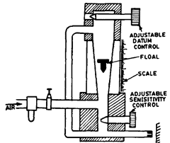
Fig. 5.42. Practical flow responsive system.
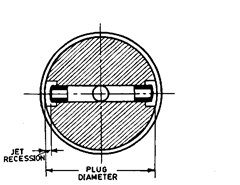
Fig. 5.43. Plug for pneumatic comparator.
5.8.1.11. Am
plification Adjustment.
This permits different range of gauge indica-
tions on same scale length and is carried out with a precision valve of the control unit. Both
zero setting and amplification adjustment should be checked from time to time depending upon
experience.
5.8.1.12.
Jet Recession.
It has already been seen that when the surface being measured
is very close to the nozzle face, equal increments of change in clearance do not produce equal
increments of pressure change. The system is not linear under these conditions.
Because of this the faces of the jets on air plug gauges are ground below the body
diameter of the plug as shown Fig. 5.43. This grinding back is called jet recession and it is the
means by which the non-linear portion at the high pressure (low flow), end of the pres-
sure/clearance curves is avoided.
5.8.1.13.
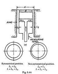
Measurement of Bore. [Refer Fig. 5.44 (a) and (6)]
In the above discussion we have as-
sumed a jet separation of the nozzle from the
flat surface. This is also applicable to measure-
ment of bore, where L is modified as :
L = Lx + L2, Lx – Radial gap for one jet
and L2 = Radial gap for other jet.
Theoretically Li should be equal to L2,
but even if L\ * L2 the back pressure would be
closely equal to that corresponding to the con-
dition L1 = L2 = L/2. This is a big advantage as
operator need not be very meticulous about
orientation of the measuring head in the bore,
and thus the readings from operator to
operator will be uniform as they do not depend
upon a high degree of operator skill or sense of
feel.
5.8.1.14.
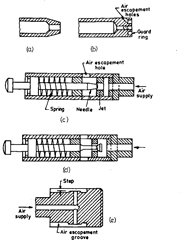
Measuring Heads Measuring heads fall under two categories,
viz. direct head [Fig. 5.45 (a) and
(6)1, and indirect or contact head [Fig. 5.45 (c)
and (d)]. Tapered nose type direct head [Fig.
5.45 (a)] is quite popular as it permits easy
access in constricted measuring conditions.
The ratio of land diameter (overall diameter at
tapered small end) compared to jet diameter is
twice in size. Bigger ratio would affect the escapement of air and the characteristics of the
system.
Head at Fig. 5.45 (b) provides good protection to the nozzle due to incorporation of guard
ring and escapement holes. In the case of indirect measuring heads, the jet is protected from
accidental damage. The size of air escapement is controlled by a needle valve or flat plate [Fig.
5.45 (c) and (d) respectively] which move due to movement of measuring plunger. By changing
the taper of needle valve, the range of measurement can be changed. Parabolic needle provides
linear response. Fig. 5.45 (e) shows the plug gauge used for measurement of diameter, lobing,
taper etc. The measuring side is made somewhat smaller than the bore so that it enters much
more conveniently.
5.8.2.
Solex Pneumatic Gauge. (Fig. 5.46).
This instrument is produced commercially
by Solex Air Gauges Ltd. This is generally designed for internal measurement, but with
suitable measuring head it can be used for external gauging also.
It is obvious from the equation for sensitivity that in order that sensitivity (magnifica-
tion) remains constant, the supply pressure P must be constant.
Thus it is necessary to have a simple pressure regulator which may control the pressure
of air from the normal supply line, and if necessary the pressure might be reduced also. The
arrangement used in Solex gauge is to pass the high pressure air after filtering, through a flow
valve. There is a tank in which water is filled upto a certain level and a dip tube is immersed
into it upto a depth corresponding to air pressure required. In Fig. 5.46, it is represented by
H. Since air is sent at higher pressure than required one, some air will leak out from the dig
tube and bubble out of water and the air
moving towards control orifice will be at
desired constant pressure H.
Now-a-days diaphragm type
pressure regulators are readily avail-
able in the market and they are better
for regulating the pressure than the
above device. The air at reduced pres-
sure then passes through the control
orifice and escapes from the measuring
jets. The back pressure in the circuit is
indicated by the head of water displaced
in the manometer tube. The tube is
graduated linearly to show changes in
pressure resulting from changes in in-
ternal diameter of the work measured.
This instrument is capable of measur-
ing to the accuracy of microns.
It is very obvious from Fig. 5.46
that the diameter being measured at
any instant is corresponding to the por-
tion against two jets. Now to find the
concentricity (roundness of any job at
any section), the workpiece may be
revolved around measuring gauge. If no
change in reading is there, then it is
perfectly round hole. Similarly the
diameter can be noted down at several
places along the length of bore and thus
tapering of hole is determined. This
method is, therefore, best suited for
measuring roundness and taperness of
cylinder bores and gun barrel bores.
By having suitable measuring
head this can be used for external gaug-
ing, and head in this case will be as
(a), (6) Direct heads (c) Forward head
(d) Reverse head (e) Plug gauge.
Fig. 5.45. Measuring heads.

Fig. 5.46. Solex Air Gauge.
shown in Fig. 5.47. This can best reveal any lobing effect
also. It is also possible to have arrangement to measure
the length of slip gauge by having the flat table and one
jet at the top.
5.8.2.1.
Overall Magnification and Range.
From equation dpIdM = 0.40 P/Mc, the pneumatic sen-
sitivity of a pneumatic measuring apparatus can be
increased by increasing the operating pressure P, but
![]()
controlled by the length of scale of pressure measuring
instrument corresponding to pressure changes from 0 to
P. If this scale length is to remain of convenient mag-
nitude, increasing the operating pressure is not a
suitable method for improving the overall magnification. The only effective method for
obtaining the higher magnification is, therefore, to reduce average separation between nozzle
and surface, which at the same time, of course, reduces the range of linear measurement.
5.8.2.2.
Limitations of empirical approach.
From the view-point of air flow, the
effective area of an orifice is not usually identical with its geometrical area. If two orifices are
made by producing holes of identical geometrical area in two thin discs, their effective areas
may be appreciably different as a result of edge effects on the air flow arising at the peripheries
of the orifices. Again the relationship between effective area and geometrical area is unlikely
to be the same for air flow through an orifice and the jet of air from a nozzle. In the experimental
determination of the p/P, MIC characteristics the value of M and C used were the geometrical
areas of orifices Om and Oc. Therefore due to effective area being different from the geometrical
area, the empirical equation obtained by analysing these characteristics would not be expected
to provide a completely accurate numerical forecast of performance.
Nevertheless, experience has shown that they do give a first approximation sufficiently
reliable to permit the required performance to be obtained by a single-step corrective adjust-
ment of the control orifice.
5.8.3.
Differential Comparators.
A later development brought out the balanced
circuit type of air-gauge. In this equipment a differential pressure indicating mechanism,
connected across the two air-paths and a built-in gauge zeroing valve is provided. Such a
balanced circuit is shown schematically in Fig. 5.48. An air gauge based on this balanced circuit
is called ‘Differential Comparator’.
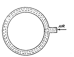
Three equally spaced measuring orifices
(jets) reveal any lobbing effect also.
Fig. 5.47

Fig. 5.48. Differential Circuit.
Compressed air from a suitable source, after passing through air-drier and filter is
regulated for constant pressure by a pressure regulator. Now the air flows into two channels,
each of which has a control orifice Ocl and Oc2 (control orifices are also called master jets).
From the control orifice Ocl, air flows to the measuring head where it meets further restriction
of the workpiece or the master settings. The restriction of the workpiece builds up back
pressure as explained earlier. At the same time, other half of the air is flowing through the
other control orifice Oc2 to the reference jet Om. By closing or opening the valve of reference jet
Om, the pressure in the space between Oc2 and Om is regulated (adjusted) to match the back
pressure from the measuring jets, which is sensed by the pressure indicating device fitted
across the two channels as shown. At this adjustment of the reference jet, the pressure indicator
would indicate equal pressure in the two channels and hence read zero on the scale. This zero
setting (adjusting of reference jet Om) is done with master workpiece whose dimension is exact
nominal size.
Now the variation of the dimension at the measuring head would cause change of
back-pressure in channel A. This pressure would be different from the mean pressure which
has been already set in the channel B (by reference jet). Now the difference of pressure of the
two channels would be indicated by the pressure indicating device which can be directly
calibrated in terms of variation of dimension from the mean dimensions. Hence the instrument
based on the measurement of differential pressure is called Differential Comparator.
If the dimension causes a decrease in gap L as compared to La, this in turn decreases
M and hence increasing back pressure in channel A and vice versa. In these cases the pressure
indicator would show readings on both sides of zero corresponding to ± deviation from master
setting.
5.8.3.1.
Advantages of Differential Circuit over Single Channel Circuit,
(i) Effect
of change of operating pressure P. The operating pressure may vary slightly from the designed
value. It can be shown that error due to change of pressure would be 0.6 to 0.8 times the change
in pressure in single channel in case of differential circuit the error would be 0.1 times the
change in pressure.
(ii) Zero setting of master gauge is an extra advantage.
(iii) Rectification for control orifice. In a single channel system, the practical limitations
may not give the perfectly correct and accurate dimension of the control orifice as designed.
Sometimes it may go out of the useful range of the design and it may have to be discarded.
Therefore, in order to avoid the error of manufacture and also to take into account the
fact that the geometrical area is different from the effective area, we need a needle valve so
that area may be adjusted accordingly.
But in the differential circuit which incorporates a needle zero adjusting valve, the
off-set of the actual size of the control orifice from the designed value can be nullified by
adjusting this valve.
5.8.4.
Non contact and Contact Type Pneumatic Gauging Elements.
Non contact
tooling is best suited for automatic gauging applications because of the advantages of no
contact, clearing of oil or foreign particles from gauging area, etc.
In the case of non-contact air gauge tooling, only the air coming out of the air escapement
orifice touches the part to be measured, the air flow rate depending on the cross-sectional area
of the jet and the clearance between the jet and the part to be measured. It may have a single
jet, two diametrically opposite jets or more evenly spaced jets. Single open-jet tooling can be
used for checking outside diameter, height, depth, straightness, squareness, etc. and Fig. 5.49
shows a few of such applications. Dual jet techniques can be applied for determining true
diameter, out or round, bell mouth, thick-
ness, etc. The various gauges may be
designed either for presenting the gauges
to part or vice versa.
Many modern mechanical as-
semblies demand that holes should be
closely controlled for straightness as well
as diameter. An air plug gauge for
gauging hole straightness is shown in
Fig. 5.50.
In the contact tooling, a mechani-
cal member is incorporated between the
air escapement orifice and the part to be
measured. The air flow from the jet chan-
ges due to displacement of this mechani-
cal member when it contacts the part.
The mechanical member could be a ball,
lever, plunger or blade. A big advantage
of contact type air gauge is that a much
bigger measuring range (upto 2.5 mm) is
possible i.e. it is suitable for wide range
of gauging. Another advantage is that it
eliminates surface roughness from
size. It may be mentioned that open
jet type method would be subject to
error for rough surfaces because it
measures a combination of size and
surface finish ; further its range of
measurement is limited. Ball jet
spindle gives a point reading rather
than the average over a small area
and is best suited for gauging inside
diameter of soft or porous parts and
for rough bores. Leaf jet spindle can
be used for checking laminated bores, blind holes in which keyways etc. do not permit the use
of open jet spindles at extreme bottom of blind holes etc. Blade jet spindles are used for
inspecting gun bores in which oil grooves, or slots do not permit the use of ball jet or leaf jet
spindles.
Fig. 5.51 shows a small plunger type air gauging cartridge which is highly efficient
size-sensing element for wide range of gauging, tooling, fixturing, and machine control
applications. It essentially consists of a spring loaded plunger. The spring tries to keep the
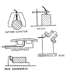
Fig. 5.49. Applications of single open jet tooling.
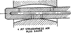
Fig. 5.50. Straightness measuring gauge.

Fig. 5.51. Air Cartridge.
plunger outwards and when the part to be measured comes in contact with it or it comes in
contact with the part it moves in and at the end restricts the orifice, thereby increasing the
back pressure. The maximum and minimum limits of the plunger movement can be set with
the help of masters. Such cartridges can be secured in gauging position on various types of
fixtures and used for measurements like height, depth, flatness, concentricity, squareness,
inside/outside diameter, etc.
Fig. 5.52 shows the same principle used in a test indicator which is very efficient for
several applications. It has a tiny stylus capable of entering into small holes, keyways, slots

Fig. 5.52. Pneumatic test indicator.
etc. and its movement causes the tapered end to act as a precision valve stem to regulate the
amount of air flowing through an orifice. It is free of hysteresis or lag or drag in indications
when the stylus is moved in any direction across the workpiece.
The contact type adjustable spindle kits and adjustable air snap gauges available in
market are found to be very suitable for handling new designs, altered dimensions and various
other varied applications.
5.8.5.
Indirect Pneumatic Gauging Devices.
The open jet has the disadvantage of
small measuring range. It can be overcome by using indirect pneumatic gauging devices by
using a gauging cartridge. Such cartridge employs a contacting stylus, the inner end of which
is tapered and forms the restriction in an escape orifice. The position of the stylus and
consequently the position of the taper in the orifice causes changes in the area of the orifice.
Changes in the rate of taper change the measuring range of the cartridge. Measuring ranges
upto 3 mm can be obtained with this type of cartridge.
5.8.6.
Air gauging with electronic sensors.
Air gauging system operate on either
low or high air pressure. While low pressure systems have greater sensitivity, quicker response
time and minimal distortion when measuring flexible components, the high pressure systems
are self cleaning type and have a large measuring range. Basically air gauging comprises air
jet gauges—such as ring or plug, and air operated liquid columns for multi-dimensional
measurement.
Now-a-days electronic flowmeters are used in place of air operated liquid columns. They
have the advantage of measuring flow of air with the added benefit of electronic display. Such
instruments can easily have 2 or 3-range selection to give an extra magnification factor.
Tolerance limit lights can be incorporated to indicate whether parts are inside or outside
manufacturing tolerances. Response time increases many folds.
The versatility of air gauging is enhanced by the wide range of measuring tools like 2
and 3 jet non-contact air plug gauges, setting rings and air jet ring gauges.
5.8.7.
Multi-gauging Systems.
Multi-gauging systems are used to measure a number
of dimensions simultaneously. Parts to be gauged are compared with a setting master which
simulates the component. The features gauged could be external/internal diameters, lengths,
straightness, squareness, ovality, run-out of faces, etc. The measuring head gauging fixture is
specifically designed to suit the component to be measured and may be completely special or
it may be built using a series of modular elements. It contains the means for sensing the
dimensional difference between the components and the master which may take the form of
mechanical or electronic probes or air jets connected to the means for amplifying the difference.
The amplifying and display of readings may take the form of dial gauges or some form
of electronic or air/electronic system.
Display may be analogue, digital or graphic and may be augmented by out of tolerance
indication.
Using electronic differential methods, the relationship between different features can
be related to a common datum.
The choice of system depends on number of factors like initial cost, dimensional
tolerances of the features to be measured, complexity of the component, complexity of the
features to be measured, number of features to be measured, speed of measurement required,
skill or otherwise of the user.
The reasons affecting the choice of displays are given below :
(i) Pointer displays—best where a rapid check of run-out or concentricity is required.
(ii) Columns—natural choice where a considerable number of dimensions are involved.
These are fastest and most convenient form of displaying the readings for every
dimension.
(iii) Digital—provides high accuracy over a longer measuring range and best for situa-
tions where it is required to work in drawing dimensions. Can be viewed without strain over
longer distances.
(iv) Graphic on VDU—the most sophisticated display essential when statistical process
control systems are employed.
Systems capable of dealing with very large number of inter-related dimensions can be
developed.
Automatic inspection machines incorporate both automated loading hopper, magazine,
pick and place robot and—automated segregation of inspected components. Automatic inspec-
tion is essential where the complexity of the component is such that manual methods can not
achieve the desired levels of accuracy.
The results of inspection could be fed to electronic computer based system which may
also control the machine operation. The use of such computer based processing also allows the
results obtained to provide a wide range of control facilities including feedback for control of
the manufacturing process.
Coordinate measuring machines accommodate multidimensional inspection by using a
single point contact to take successive measurements over the component profile. The contact
movement and processing of the dimensional information is under computer control, which
can also provide similar facilities to those offered by multi-point gauging.
