7.7.
7.7.1.
Parallelism.
First we shall be dealing with the parallelism of lines and planes,
and then the parallel motion. Let us first understand what we mean bv ‘line’ or ‘axis’ in
metrology. An axis is represented by cylindrical sur-
face of high precision of form, suitable surface finish
and sufficient length. Under certain circumstances,
test mandrels have to be used. These are fixed and
centred on the end of the shaft or in the cylindrical or
conical bore designed to take it. It may be understood
that when a mandrel is employed to represent the axis
of rotation of spindle etc. it is not necessary that mandrel might have been exactly centred and
under such a case the axis of the mandrel on rotation may describe a hyperboloid, or a conical

Fig. 7.7. Parallelism of lines.
surface if the axis of the mandrel intersects that axis of rotation and gives two extreme positions
P and P’ lying in the plane of test. Under such circumstances, two readings should be taken,
one in any position and the other after rotating the spindle by 180° (e.g., two positions D and
Z^’oFdial indicator in Fig. 7.7), and their mean taken.
We shall now study the various cases of parallelism of lines and planes.
(a) Parallelism of two axes
. This test is made in two planes, first plane being the one
passing through one of the two axes and as near as
possible to the second axis, and the other plane is
perpendicular to the first one.
In this test, the dial indicator is held on a sup-
port with a base of suitable shape, so that it slides
along a cylinder representing one of the two axes; and
the dial indicator is adjusted so that its feeler slides
along the cylinder representing the second axis. The
maximum deviation between the axes at any point may
be determined be gently rocking the dial indicator in a
direction perpendicular to the axes. In the same way
the parallelism may be tested in the perpendicular
plane.
(b) Parallelism of two planes.
Two planes are said to be parallel, when their distance
from each other is measured anywhere on the surface and at least in two directions, and the
maximum error (the difference between the maximum and the minimum dimensions obtained
when measuring) over a specified length does not exceed an agreed value.
The test for parallelism of two planes is carried out in two directions (generally
perpendicular to each other). The dial indicator, which is held on a support with a flat base, is
moved in one plane over a given length, and the feeler is made to rest against the second plane ;
and the deviations noted down (Fig. 7.9).
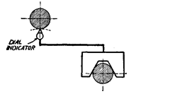
Fig. 7.8. Parallelism of two axe.
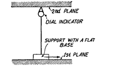
Fig. 7.9. Parallelism of two planes.
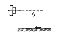
Fig. 7.10. Parallelism of an axis to a plane.
(c) Parallelism of an axis to a plane.
An axis is said to be parallel to a plane, if the
maximum difference between the several readings taken while measuring the distance of line
from plane at a number of points, does not exceed a predetermined value. In testing, the feeler
of the dial indicator is made to touch the surface of the cylinder representing the axis and the
dial indicator (held on a support with a flat base) is moved along the plane by the specified
amount (length over which the test is to be performed) (Fig. 7.10). At each point of measurement
the shortest distance is found by slightly moving the indicator in a direction perpendicular to
the axis.
(d) Parallelism of an axis to the intersection of two planes.
The test set up is shown
in Fig. 7.11 and this test is also conducted in two perpendicular planes of the greatest
importance.
(e) Parallelism of the intersection of two planes to a third plane.
This test is
similar to the one given above. The feeler instead to touching the cylindrical surface touches
the third plane to be tested. The feeler is set at right angles to the plane.
(f) Parallelism between two straight line,
each formed by the intersection of
two planes. The test set-up for checking the parallelism in two perpendicular planes is shown
in Fig. 7.12. This set up is used in cases where the distance between two lines is small. If
distance is large then the V-blocks are covered by a straight edge and check made by a spirit
level.
The tolerance (permissible deviations) of parallelism of straight lines or plane surfaces
are specified as:
0.015 mm on 300 mm (free end of spindle in upward direction only relative to the table
surface).
If considered desirable, the tolerance of the form of feeler surface should also be specified.
7.7.2.
Parallel Motion.
The term ‘parallel motion’ refers to the position of the trajectory
of a moving part of the machine in relation to a plane (support or slideway in case of machine
tool), a straight line (axis, intersection of planes), and a trajectory of a point on another moving
component of the machine. The tolerance on parallelism of movement is the permissible
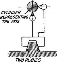
Fig. 7.11. Testing parallelism of an axis
to intersection of two planes.
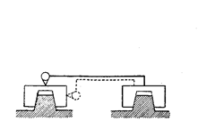
Fig. 7.12. Testing parallelism of two lines formed
by interaction of two planes.
variation in the shortest distance between the trajectory of a given point on the moving part
and a plane, a straight line or another trajectory within a stated length. As a general rule,
unless all planes are of equal importance, the checks are made in two perpendicular planes
selected as being those of most importance for the practical use of the machine.
The test for checking parallel motion in various cases are performed as below :
(a) Parallelism between a trajectory and a plane
(i) When the plane is on the moving components itself. In this case the dial indicator is
attached to a fixed component of the machine and its feeler adjusted at right angles to the
surface to be tested. The moving component is moved by the specified amount and the
deviations noted down.
(ii) When the plane is not on the moving component itself. The set up for this test is shown
in Fig. 7.14.
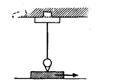
Fig. 7.13. Testing parallelism between a trajectiory
and plane/on moving component.
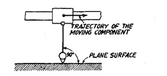
Fig. 7.14. Testing parallelism between a trajectory and
a plane (not on moving component).
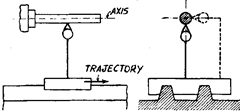
Fig. 7.15. Test set uf for testing parallelism
of a trajectory to an axis.
(b) Parallelism of a trajectory
to an axis. The test set up is shown in
Fig. 7.15.
(c) Parallelism between two
trajectories. In this test, the dial in-
dicator is attached to one of the moving
components of the machine and its feeler
made to rest against a given point on the
other moving part. The two parts are
moved together in the same direction by
the same amount, and the variation in
the reading noted (Fig. 7.16).
7.7.3.
Equidistance.
It relates to the distance between the axes and a reference plane.
There is equidistance when the plane passing through the axes is parallel to the reference
plane. It may be different axes, or the same axis, occupying different positions after pivoting.
The method of measuring the
equidistance is in effect identical with
that of measuring parallelism between
a plane passing through the axes and a
reference plane. The test consists in
first testing that the two axes are paral-
lel to the plane and then testing that
they are equidistant from this plane.
For this purpose, a dial indicator is
made to rest on the reference plane and
with the same gauge, readings are
noted on the cylindrical surfaces repre-
senting the two axes by sliding the dial
gauge on the reference plane (Fig. 7.17).
If the two cylinders are not identical,
then the difference of radii of the tested
sections should be taken into account.
In the second case where the
same axis occupies different positions
after pivoting and where the plane of
pivoting is not accessible for allowing
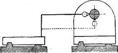
Fig. 7.16. Test set up for testing parallelism
between two trajectories.

Fig. 7.17. Testing equidistance.
movement of the instrument, an additional plane is constructed parallel to the plane of
pivoting; the setting and fixing of the auxiliary plane is carried out so that, when a level is
placed on it, if possible, in two perpendicular directions, there is no deviation during the
pivoting motion of the component. The equidistance of the pivoting axis is then tested both in
the middle as well as extreme positions.
7.7.4.
Coincidence or alignment.
Many a times this word is used with more general
meaning of parallelism. For metrology purposes this term refers to two axes merged in each
other or where one axis extends beyond the other.
Two lines or axes are said to be coincident or in alignment when their distance apart at
several points over a given length is measured and this distance does not exceed a given value.
The distance measured may be located either on the actual lines or on their prolongation.
The tolerance on alignment of two axes is specified as under: When the direction of the
permissible deviations in alignment of two axes (or two lines) does not matter, the tolerance
is given as : Error of alignment of axis 1 to axis 2……………(x or mm over a given length.
In special cases an additional indication depending on operating conditions may be
given, for instance:
‘axis 1 only higher than axis 2′, or ‘free end of axis 1 directed only outwards in relation
to axis 2′.
In other cases, it may be useful to introduce beside the tolerance on coincidence, an
additional tolerance, on parallelism between the two axes (Fig. 7.18). In this figure,
(a) ‘Error of alignment of axis 1 to axis 2 : T \i or mm over a given length’.
(b) ‘Error of parallelism between axis 1 and axis 2 : T n or mm over given length
(T> T)’.
Coincidence between two lines or axes is measured by the method given below. In case
when both the axes whose coincidence is to be tested are fixed, then for one of the axes a mandrel
is used to represent the axis (2nd axis
in Fig. 7.19) ; and the dial indicator is
attached to an arm and rotated
through 360° around the other axis.
(Fig. 7.19 shows the other axis, i.e.,
first as the axis of rotation). The feeler
of the instrument is adjusted to touch
the surface of the mandrel and any
variation in the reading represents
twice the error of coincidence. Check is
generally made into two planes be-
cause the first plane chosen may
intersect both axes. When one of
the axes is the axis of rotation,
then arm carrying the dial indic-
tor is mounted on a ring of suffi-
cient length (in order to ensure
that the reading is not affected by
play in the ring) and rotating with a minimum amount of play (Fig. 7.19).
In this test, the dial indicator of very light weight should be used, as the direction of the
measurement varies during rotation in relation to the direction of gravity, and if possible the
sensitivity of the test apparatus to the force of gravity should be taken into account.

Fig. 7.18. Error of alignment of axis vis a vis error
of parallelism of axes.
![]()
Fig. 7.19. Testing coincidence between two axes.
