17.7.
In these instruments, light beam is used as the amplifying lever. The light beam has the advantage of straightness and weightlessness. The optical measuring instruments include:
(i) Vertical optimeters. (ii) Horizontal optimeters. (iii) Tool maker’s microscope. These are used for highly precise measurements.
17.7.1.
Vertical optimeter.
It is mainly designed for external measurements of shafts, plates ; and can also be used for checking plug gauges and for varifying the slip gauges. The instruments are available in the range of measurement of 0 to 180 mm.
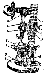
The general view of the instrument is shown in Fig. 17.7. It comprises the upright I mounted rigidly in a base 2. The base is made very heavy and wide so that it imparts ample
stability to the instrument. The upright consists of a ground shaft on which a large pitch thread of special form is cut so that it could provide an easy grip for the bracket 3. The bracket 3, which is integral with the split clamp 4 can be easily moved up and down and adjusted and fixed in any position along the upright 1. The bracket 3 is clamped on the upright at any required position by the binding screw and raised or lowered by nut 10 mating with the special thread of the upright. The optimeter tube 5 which is of right-angular design is held by the split
1. Upright.
2. Base.
3. Bracket.
4. Split clamp.
5. Optimeter tube (Measuring head).
6. Binding screw.
7. Optimeter table.
8. Upper table.
9. Adjusting nut. 10. Nut.

Fig. 17.7. Vertical Optimeter.
clamp 4 and is secured in position by the binding screw 6. The optimeter tube 5 can also be adjusted vartically in the clamp 4. The upper (working table) 8 is mounted on the optimeter table 7 and is under the measuring tip of optimeter tube. The distance between the measuring tip and the table is adjusted in two ways. The coarse adjustment is made by raising or lowering the bracket 3 and fine adjustment is made by raising or lowering the tables 7 and 8 by means of the adjusting nut 9. After setting up the instrument and before making measurement, all clamping screws of the brackets and tables must be firmly tightened.
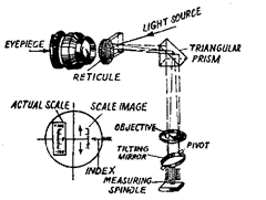
In the optimeter tube, measurements are made by the comparative method. The optimeter tube is of right-angle design. It consists of the measuring tip formed by a measuring spindle, at the bottom of which is secured a ball-shaped contact point. The optical system of
the instrument is shown in Fig. 17.8. The movement of the measuring spindle (ball-shaped tip) is transmitted to a tilting mirror, at the top of which is placed an abjective. There is an eyepiece placed at right angles to the movement of tip. Through the eyepiece scale deviations are observed. There is a flat circular disc made of glass (reticule) on which scale is engraved. The disc is graduated on the side facing the triangular prism. The triangular prism is used to reflect the beam of light by 90°. The beam of light obtained from an electric lamp is directed by the hinged mirror to the scale on disc. The disc is covered with black photographic paper in which slots are provided. One such slot is opposite the scale. The reflected beam of light first passes through the triangular

Fig. 17.8. Optical system of optimeter.
prism, then through the objective to the tilting mirror. For the initial position, only the position of the actual scale is seen through the eyepiece. Now if the mirror is tilted by the measuring spindle and is inclined in reference to the direction of the beam of light, beam will be reflected at a certain angle and returned to the eyepiece. The reflected image of the scale will be slightly displaced on the glass disc in reference to the index line. The amount of displacement can be easily read on scale of the disc.
The reflected image of the scale is visible in the eyepiece because it is projected on the glass disc symmetrically on the other side of the optical axis in reference to the scale engraved on the disc. The slots in the paper covering the glass disc are arranged in such a way that the actual scale engraved on the disc is not visible and only the reflected scale is visible. The amplification of the instrument is equal to the
![]()
It’s value is of the order of 1000. The scale has about 200 divisions and a range of measurement of ± 0.1 mm. As already pointed out, the instrument works on comparison basis, and therefore, the measuring tip is first set to the required dimension in relation to the table by means of slip gauges and then the component to be measured is placed on the table in place of slip gauges.
17.7.2.
Horizontal Optimeter.
The horizontal optimeter is in a way similar to the vertical optimeter, particularly the measuring head (tube) is the same for both the designs. It differs from the vertical type in the following features :
(i) The axis of the measuring spindle is horizontal.
(ii) The range of external measurement is from 0 to 500 mm.
(iii) The internal measurements in the range 13-180 mm is with the aid of auxiliary contact arms.
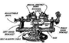
The design of the horizontal optimeter with set up for measuring internal surfaces is shown in Fig. 17.9.
The instrument consists of a wide base on which is supported a horizontal bar. The two brackets (right hand and left hand) move along this horizontal bar and can be adjusted in any position to a distance of 500 mm. For external measurements, the optimeter tube is secured in the right hand bracket, and the adjustable anvil which is having the same functions as the table in a vertical optimeter is supported on the left-hand bracket. The

Fig. 17.9. Horizontal optimeter.
part to be checked is placed on the rotary table which can be adjusted in any direction. The rotary table itself rests on another self-aligning table which can be set in any position.
While using the instrument for internal measurements, two special contact arms are mounted on inner side of adjustable anvil and the optimeter tube. The contact arms carry the rocking links with the contact tips which come in contact with the internal part to be checked as shown in Fig. 17.9. The movement of the contact tips due to variation in the surface to be checked is transmitted to the contact point of the optimeter tube through the rocking links. The distance
between the two contact tips is set upywith a master ring gauge or with slip gauge.
17.7.3.
Toolmaker’s microscope.
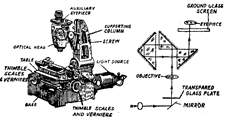
A general view of the small model toolmaker’s microscope giving its design, and its optical system is shown in Fig. 17.10. This is designed for measurements on parts of complex forms e.g. profile of external threads, tools, templets and gauges. It can also be used for measuring centre-to-centre distances of holes in any planes, as
well as the co-ordinates of the outline of a complex templet gauge, using the co-ordinate measuring system.
Basically, it consists of the optical head which can be adjusted vertically along the ways of a supporting column. The optical head can be clamped in any position by a screw. The working table on which the parts to be inspected are placed, is secured on a heavy hollow base. The table has a compound slide by means of which the measured part can have longitudinal and lateral movements. These movements are controlled by

Fig. 17.10. Small toolmaker’s microscope.
accurate micrometer screws having thimble scales and verniers. At the back of the base is arranged a ligh source which provides a horizontal beam of light which is reflected from a mirror by 90° upwards towards the table. The beam of light passes through a transparent glass plate on which flat parts to be checked are placed. A shadow image of the outline of contour of the part passes through the objective of the optical head and is projected by a system of three prisms to a ground-glass screen. Observations are made through the eyepiece of the optical head.
Cross-lines are engraved on the ground-glass screen which can be rotated through 360°, and the measurements are made by these cross-lines. The angle of rotation of screen can be read through an auxiliary eyepiece provided on the optical head. The eyepiece field of view contains an illuminated circular scale with a division value of 1 minute. The optical head tube is adjusted in height for focussing purposes, till a sharp image of the projected contour is seen on the ground glass screen.
Different types of graduated and engraved screens and corresponding eyepieces are used for measuring different elements e.g., a revolving screen for measurement of standard threads will contain all the basic profiles of all standard threads in various pitch ranges and also various included angles of the threads.
Measurement of screw thread pitch. The image of the thread profile is set so that some point of the profile coincides with the cross-hairs as seen on the ground-glass screen. The reading on thimble of the longitudinal micrometer screw is noted down. Then the part is traversed by the micrometer screw until a corresponding point on the profile of the next thread coincides with the cross-hairs. The reading on thimble is again noted and the difference in two readings gives the actual pitch of the screw.
Measurement of angle of thread. It is determined by rotating the screen until a line on the screen coincides with one flank of the thread profile. The angle of screen rotation is noted and then the screen is further rotated till the same line coincides with the other flank of thread. The difference in two angular readings gives the actual angle of thread on the screw.
17.7.4.
Atomic Force Microscope.
An Atomic force microscope (AFM) is a very precise and multi functional device for measurement and visualisation of micro surface structure. The AFM uses sharp scanning of the surface of a sample. The sample is mounted on a piezo ceramic, which can be moved in three perpendicular directions. The sample can be scanned in horizontal (x andjy) directions under the sharp tip. The tip is fixed at the free end of a cantilever on which a laser beam is focussed. The light from the laser is reflected on a split photo diode. By
measuring the difference in signal, changes in the bending of the cantilever can be measured. In this way the topographical map of the sample can be produced with the vertical with resolution of 1 nm. A laser beam with a minimum spot size of less 0.06 urn for 50 x 0.55 numerical aperture objective for X = 632 nm is focussed on the surface of the object and is moved to the required distance by auto tracking and autofocusing. The movements result in a 3-D profile corresponding to the surface profile. An atomic force microscope (AFM) can reveal a smple surface precisely up to nanometer size in three dimensions. Due to the sharper tip and very small loading force, the lateral resolution in AFM is largely improved when compared with that of the conventional profilometer.
