17.2.
The general form of measuring machine called length bar measuring machine used to
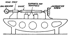
determine the length of a pin gauge consists of a long bed having vee and flat guide ways along the bed to allow suitable spacing of measuring head, anvil and work supports (Fig. 17.1). A fixed headstock and a movable tailstock each with a measuring face anvil are carried on the bed. A micrometer screw fixed on tailstock is used as a means of revealing difference in length between a setting master and workpiece. The

Fig. 17.1. Length-bar measuring machine.
machine can show the length of the work either by direct comparison with standard length bar or by the use of an accurate “built in” scale. In either case the tailstock has to be moved to such a position that the two anvils are just touching the end of the workpiece which is supported parallel to the bed of the machine. This is achieved by using a micrometer screw in tailstock and a sensitive indicator (dial gauge) in the headstock. Difference between the settings required for standard bar and workpiece is measured by the micrometer screw in the tailstock. The headstock anvil is carried in such a way as to show when contact is made with the workpiece. This part of the machine is so sensitive that the reading of the tailstock setting on any workpiece can be repeated to 1/40 (i.e. fortieth part of a mm). For correct measurement, the correct support in horizontal plane is very essential and for this the two support points should be spaced 0.577 L apart, L being the length of the workpiece. The supports used are of vee form and adjustable for height, and spacing laterally across the bed. This machine has two
special features which are essential in any set-up for fine measurement i.e., the piece to be measured is positively located in relation to the measuring faces and the contact between measuring faces is proved mechanically without relying on any personal element.
When the length of any bar is to be measured, a length bar of appropriate grade whose dimensions are exactly known is placed over the vee supports which are then adjusted in height so that axis of the bar and axis of measurement are coincident. A reading on micrometer is then noted for some suitable position of the pointer of the dial indicator. The gauge is then replaced by the bar whose dimension is to be determined and a second micrometer reading is taken at the same reading of the dial indicator. The difference between two micrometer readings is then the difference between the length of the setting standard and the work. Its
![]()
movement of the screw the length of setting master should be close to the length of the workpiece. Before taking any readings, temperature stabilization should be attained for accurate results.
Length Bar Measuring Machine (Metrology)
Next post: Universal Measuring Machine (Metrology)
Previous post: Measuring machines (Metrology)
