23.16.
Metrology lasers are low-power instruments. Most are helium-neon continuous-wave output lasers that emit visible or infrared light. He-Ne lasers produce light at a wavelength of 6328 A (0.6 pi) that is in phase, coherent, and a thousand times more intense than any other monochromatic source.
Laser inspection systems enable measurement of a part as it is produced, thus permitting 100% quality. Laser systems have wide dynamic range, low optical cross talk, and high contrast.
Lasers find applications in dimensional measurements and surface inspection because of the properties of laser light (bright, unidirectional, collimated beam, with a high degree of temporal and spatial coherence). These are useful where precision, accuracy, rapid non-contact gauging of soft, delicate, hot or moving parts is called for.
Various technique for dimensional measurements are :
(i) Scanning Laser Gauge. Fig. 23.13 shows a schematic diagram of a scanning laser gauge. It basically utilises a transmitter, receiver and processor electronics. A thin band of scanning laser light is made to pass through a linear scanner lens to render it parallel beam. The object placed in a parallel beam, casts a time-dependent shadow. Signals from the light entering the photo cell (receiver) are processed by a microprocessor to provide display of the dimension represented by the time difference between the shadow edges. It can provide results to an accuracy of + 0.25 um for 10-50 mm diameter objects. It can be used for objects 0.05 mm to 450 mm diameter and offers repeatability of 0.1 um.

Fig. 23.13. Schematic of scanning laser gauge.
(ii) Photo Diode Array Imaging.
In this method, shadow of stationary part is projected on a solid-state diode array image sensor. The system comprises of laser source, imaging optics, photodiode array, and signal processor and display unit. For large parts, two arrays, one for each edge are used. Accuracies as high as + 0.05 um have been achieved.
(iii) Diffraction Pattern Technique.
These are used to measure small gaps and small diameter parts. In this method, a parallel coherent laser beam is diffracted by a small part, and the resultant pattern is focussed by a lens on a linear diode array. Since diffraction is not suitable for diameters larger than a few millimeters, its use is restricted to small wires, etc. The measurement accuracy is more for smaller parts. The distance between the alternating light and dark bands in the diffraction pattern is a direct function of the wire diameter, wavelength of laser beam, and the focal length of the lens.
(iv) Laser Triangulation Sensors.
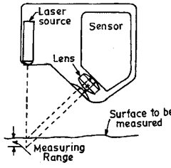
Fig. 23.14 shows the principle of laser triangular sensor. A finely focussed laser spot of light is directed at the part surface. A lens in the sensor images this bright spot onto a digital solid-state, position-sensitive photo detector. The measuring range is very small. The stand off distance is calculated and fixed carefully. The location of the image spot is directly related to the stand off distance from the sensor to the object surface. A change in the standoff distance results in a lateral shift of the spot along the sensor array. This technique provides quick measurement of deviations due to changes in surface and thus it can perform automatic

Fig. 23.14
calculations on shell metal stampings for gap and flushness, hole diameters, and edge locations very quickly. It is possible to measure part thickness or the inside diameter of bores by using two sensors. The accuracy of measurement and range of measurement are directly related.
(y) Two-Frequency Laser Interferometer.
Fig. 23.15 shows schematic arrangement comprising of two-frequency laser head, beam directing and splitting optics, measurement optics, receivers, wavelength compensators, and electronics. It is ideally suited for measuring linear positioning, straightness in two planes, pitch and yaw. The two-frequency laser head provides, one frequency with a P polarisation (measuring beam) and another frequency with an S polarisation (reference beam). The laser beam is projected to a remote interferometer and is split at the polarising beam splitter into its two separate frequencies. The measuringjieam is directed through the interferometer to reflect off a target mirror or retroreflector attached to the object to be measured.

Fig. 23.15
The reference beam is reflected from fixed retroreflector. The measurement beam on its return path recombines with the reference beam and is directed to the electronic receiver. A frequency shift is induced into the returning measurement beam by Doppler effect due to movement of the target mirror. Because of their orthogonal polarisation, the frequencies do not interfere to form fringes until the beam reaches the receiver which monitors the frequency shift and provide output of the displacement.
The advantage of this technique lies in independence of system on the beam intensity and thus it provides high sensitivity, being independent of noise due to air turbulence, electrical noise, and light noise. Laser head can be mounted any where. Further due to use of single photodetector per measurement axis, sensitivity to optical alignement is less. The linear resolution of this method is 1 nm, straightness resolution is 40 nm and angular resolution is 0.03 arc seconds.
(vi) Laser Scanning Gauge.
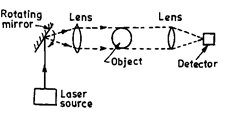
Fig. 23.16 shows a laser scanning gauge used for non-contact measurement of large objects to an accuracy of about 0.01 mm using the low divergence
of a laser beam. A rotating mirror at the focus of the first lens produces a beam parallel to the optic axis. The time between the leading edge of the beam being extinguished by the object and when it emerges from the other side is a measure of the cross-section which is a function of the tangent of the angle subtended by the object at the focus of the first lens. This technique is useful to measure the roundness and diameter of hot steel bars under conditions of vibration to an accuracy of 0.025 mm over diameters of 5-25 mm.

Fig. 23.16
(vii) Gauging Wide Diameter from the Diffraction Pattern formed in a Laser Beam. Fig. 23.17 shows a method of measuring the diameter of thin wire using the interference

Fig. 23.17
fringes resulting from diffraction of the light by the wire in the laser beam. The detection of a null magnified to fill the dectector’s aperture indicates that the wire is outside its dimensional tolerance. The system uses the changes in fringes formed by diffraction with wire diameter which cause a variation in the output from the photodetector and can be used as part of a control system or warning indicator.
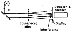
A measure of the diameter can be obtained by moving the photodetector until the output is restored to its original value. Changes in wire diameter as small as 0.2% over wire diameters from 0.005 to 0.2 mm can be measured. Fig. 23.18 shows the method of length measurement
by fringe counting. The laser output, which may be incoherent, illuminates three slits at a time in the first plane which form interference fringes. The movement of the interference fringes is determined by a detector on the other side of a short length of conventional Moire grating. The total number of slits in the first plane is governed by the length over which measurement is required. The spacing between the slits and distance of the slit to the plane of the grating depend on the

Fig. 23.18
wavelength of the light used. Using He-Ne laser at 0.63 um, a fringe spacing of 1 um is obtained at 1.4 um from the slits if a slit separation of 1 um is used.
This method is capable of accurate measurements over relatviely short distances of the order of 100 mm independent of variation of refractive index and turbulence in air path.
