7.4.
Like straightness testing, the simplest form of flatness testing is possible by comparing
the surface with an accurate surface. One of the surfaces is marked with Prussian blue and
the other surface rubbed over it. The distribution of colour over the other surface gives a rough
idea of high and low points on the surface. This method is usually suitable for small plates and
not for large surfaces.
Mathematically, flatness error of a surface states that the departure from flatness is
the minimum separation of a pair of parallel planes which will just contain all points on the
surface. The deviation of a large surface such as surface table or machine table from the true
plane may be determined by the use of either a spirit level or an auto-collimator. The principle
of the method is same, whether the apparatus used is auto-collimator or spirit level.
According to IS : 2063—1962, a surface is deemed to be flat within a given range of
measurement when the variation of the perpendicular distance of its points from a geometrical
plane (this plane should be exterior to the surface to be tested) parallel to the general trajectory
of the plane to be tested remains below a given value. The geometrical plane may be
represented either by means of a surface plane or a family of straight lines obtained by the
displacement of a straight edge or a spirit level or a light beam :
Flatness deviations (errors of flatness) are indicated as follows :
(i) … µor mm per metre when convexities are allowed as well as concavities ;
(ii) concave to … |x or mm, when, between the ends, only concave surfaces are allowed ;
and
(iii) convex to … \x. or mm, when, between the ends, only convex surfaces are allowed.
It is well known that a surface can be considered to be composed of an infinitely large
number of lines. The surface will be truly flat only if all the lines are straight and they lie in
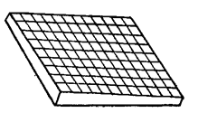
the same plane. Let us study the case of rectangular table. From Fig. 7.4, it is obvious that all
the generators (lines) are straight and parallel to the sides
of the rectangle in both the perpendicular directions. Even
then it is not truly flat, but concave and convex along two
diagonals. Thus for the verification of a surface to be truly
flat, it is essential to measure the straightness of diagonals
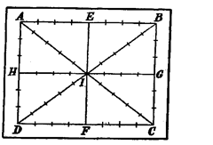
in addition to the lines parallel to the sides. Thus the whole
of the surface is divided by straight lines as shown in Fig.
7.5. The end lines AB and AD etc., are drawn away from the
edges as the edges of the surface are not flat but get worn
out by use and can fall off little in accuracy. The straightness
of all these lines is determined and then those lines are related with each other in order to
verify whether they lie in the same plane or not. In above setting of the lines, it should be kept
in mind that the lines are whole multiples of the length of base of spirit level or reflector stand
and the centre of the diagonals. I must be one of the contact points of the feet of the block.
7.4.1.
Procedure for determining flatness (Fig. 7.5).
The procedure for determining
flatness is as follows :
(1) Carry out the straightness test already described on all the lines AB, BC, AC etc.
and tabulate the readings upto the cumulative error column.
(2) Let a plane passing through the points A, B and D be assumed to be an arbitrary
plane, relative to which the heights of all other points
may be determined. For it, the ends of lines AB, AD
and BD are corrected to zero and thus the height of
points A, B and D are zero.
(3) The height of point / is determined relative
to the arbitrary plane ABD = 000. As I is the mid-point
of lineAC also, all the points on AC can be fixed relative
to the arbitrary plane by assumingA = 0 and correcting
/ on AC to coincide with the mid-point J on BD. In this
way, all points on AC are corrected by amounts propor-
tionate to the movement of its mid-point. A hint could
be taken here that C is twice as far from A as the
mid-point, the correction for C will be double that oil.
(4) Point C is now fixed relative to the arbitrary plane and points B and D are set at
zero, all intermediate points on BC and DC can be corrected accordingly.
(5) The positions of H and G, E and F are known, so it is now possible to fit in lines HG
and EF. This also provides a check on previous evaluation since the mid-point of these lines
should coincide with the known position of mid-point I.

Fig. 7.4. Testing flatness.

Fig. 7.5. Flatness testing procedure.
In this way, the height of all
the points on the surface relative to
the arbitrary plane ABD are known.
One thing to be noted here is
that according to definition of flat-
ness error, departure from flatness is
determined by the minimum separa-
tion of a pair of parallel planes which
will just contain all the points on the
surface. Here it is possible to deter-
mine two points at either extreme of
the reference plane to define the
separation but the reference plane
chosen may not be the best plane.
Therefore, in order to determine the
minimum separation some correction
has to be made. The calculation for a
final correction to determine the min-
imum separation of a pair of parallel
planes which just contain all the
points on the surface is made by
graphical method as given below.
The various points on the sur-
face have been determined with ref-
erence to ABD as reference plane as
described previously. Two points on
opposite sides having maximum posi-

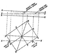
Fig. 7.6. Minimum separation of parallel planes containing
all points on surface.
tive and maximum negative values are selected and jointed together by a line XX. Let these
points in Fig. 7.6 be R and S. Draw a line IT parallel to XX to represent the plane ABD as
shown in Fig. 7.6. Set off to scale the height of all points relative to YYby taking projections
from all the points on the surface.
In Fig. 7.6, projections from all points have not been shown for the sake of clarity. Next
by inspection, draw a closest pair of parallel lines ZZ and ZZ, which will contain all of the
points. It may be noted that one line will have two points on it, and the other line, one point
only. The distance between these two lines is a measure of the error in flatness. Although it is
not exact value but for practical purpose it gives sufficiently accurate results.
The optical flatness testing method for very flat and polished surface has already been
discussed in the chapter of Interferometry.
