1.15.
1.15.1.
Effects of Environment—Temperature.
Many applications specify tolerances in
microns. It may be appreciated that 25 mm of steel will lengthen about 0.3 microns when its
temperature is increased by 1°C. Obviously for precision measurements in terms of microns, error
of 0.3 microns just by change of 1°C temperature is substantial. It should be understood that a piece
of steel held in the hand absorbs heat very fast and upto 5°C rise in temperature can be expected
in 5 minutes time, but it would take hours for it to cool to the laboratory temperature and obtain
its original length. It would thus be realised that temperature has a great influence on accuracy of
precision measurements. For such accuracy, it is essential that the gauge blocks and workpieces
are handled with insulated forceps, or tweezers, with plastic pads or gloves. Usually a plastic shield
is introduced in between the inspector and the machine so as not to influence temperature of
machine surroundings due to presence by body radiant heat or hot breath or in any other way. In
some interferometers, the machine is entirely enclosed in a box with transparent plastic and the
operator manipulates the parts with long-handles, insulated forceps introduced through self-sealing
rubber part holes. Prior to measurement, the parts, gauges and masters are all stored on the heat
sink till they are stablised at the controlled room temperature. Heat sink consists of a slab of steel
or aluminum of considerable mass with a clean-smooth surface.
To maintain such controlled temperature in air-conditioned gauging laboratory is essential.
The cool air should be so deflected and diffused that the temperature in room will be same in any
location but there should be no direct air currents to be noticed.
It may be mentioned that infra red rays from direct sunlight on the gauge would also tend
to heat it even in air-conditioned room and, therefore, the sun rays should not enter the laboratory.
Thus the stable atmospheric environment free from stray erratic temperature variations and
soaking of gauges, masters and workpiece in heat sinks are essential for precise measurements.
The temperature of the room should be measured precisely and recorded at regular intervals in the
vicinity of gauges.
Internationally accepted temperature for measurement is 20°C and all instruments are
calibrated at this temperature. In case workpieces and measuring instruments are of same material
then there would be no need of maintaining temperature constant since both would expand equally.
But different materials expand differently and hence the need of maintaining constant temperature.
Whenever gauges and workpieces have to be handled, as in the case of wringing of slip
gauges, etc., these should be left on table for about an hour in order to enable them to attain uniform
temperature of 20°C.
1.15.2.
Effect of supports.
In the case of long measuring bars, straight edges, these have
been supported as a beam. The amount of their deflection due to supporting depends on the position
of the supports. Slope and deflection at any point can be calculated by means of expressions derived
from the theory of bending.
For a bar of length L, supported equidistant from the centre on supports by distance I apart,
then for no slope at the ends, l/L = 0.577, and for minimum deflection of the beam, l/L = 0.554.
First condition is required for supporting standard bars and second condition is required in
case of straight edges.
If a straight edge of rectangular section is quite true when laid on its side on a flat surface,
it will not be straight when supported with its edge horizontal. The deflection is minimum when it
is the same at the ends and the center. The necessary spacing of the supports is found by utilizing
the mathematical relations for the bending of beam giving I /L equal to 0.554.
1.15.3.
Effect of alignment.
Abbe’s principle of alignment should befollowed in measure-
ments to avoid cosine errors, sine errors, etc. According to this principle, the axis or line of
measurement of the measured part should coincide with the measuring scale or the axis of
measurement of the measuring instrument. Cosine error occurs in measuring the length of any part
with a scale if the measuring scale is inclined to the true line of dimension being measured. In
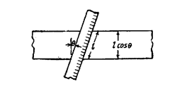
Fig. 1.7. (a) Cosine error.
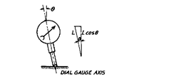
Fig. 1.7. (b) Errors due to non-alignment of
plunger axis and line of measurement.
Fig. 1.7 (a) it may be seen that the length recorded is in excess of the true length by an amount
Z(l- cos 8). However, this error is negligible in most cases since the angle 6 is usually very small.
An alignment error of 2° over 1 metre introduces an error of approximately 0.6 mm.
Similarly error is introduced to dial indicator readings if the plunger axis does not coincide
with the axis or line of measurement as in Fig. 1.7 (b).
![]()
To ensure correct displacement readings on the dial indicator, the plunger must, of course,
be normal to the surface in both mutually perpendicular planes.
The measuring jaws of the vernier caliper are in effect extension of the scale markings on
the instruments ; thus the jaws of an instrument in good condition are parallel and remain so at
any measurement within the instrument range. The
length I indicated on the scale corresponds to the
displacement of the jaws from each other as in Fig.
1.8 (a). The effect of a bent scale beam is shown in
Fig. 1.8 (b). The length l\ between the extremes of the
jaws has now become smaller than the length indi-
cated on the scale. It is also evident that the error
introduced is proportional to the length of the jaws
and is at its minimum along the graduations line of
the scale.

f lg. 1.8. Error introduced due to bent jaws
of the vernier caliper.
Similar errors occur in the case of an indicator fitted with a ball-end stylus arm. In this case,
it is important for the arm to be set so that the direction of movement of the work is tangential to
the arc long which the ball moves. In both the cases of Fig. 1.9 (a) and (6), the reading on the indicator
will be h sec 6, where h is the distance moved by the work. It may be remarked that some lever type
test indicators are designed for use with their styli inclined at about 30° to the line of measurement
and in these cases, an error would occur if it were set with the stylus normal to the line of
measurement.
The combined sine and cosine errors occur when measuring an end gauge in the horizontal
comparator if the gauge is so supported that its axis is
not parallel to the axis of the measuring anvils, or if its
each end, though parallel to each other, are not square
to the axis.
With reference to Fie. 1.10
![]()
Errors of the above nature can be avoided by
using gauges with spherical ends. It may be noted that
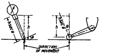
Fig. 1.9. Sine error.
such gauges need not be aligned accurately when used combination. Fig. 1.11 shows two gauges of
this type with their axes out of line by an amount 5. The error in their combined length is very
small, (a + b).
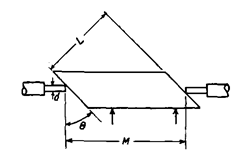
Fig. 1.10. Both sine and cosine errors.
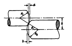
Fig. 1.11. Errors when spherical end gauges are
not properly aligned.

With 150 mm and 250 mm gauges out of line by 0.2 mm, the error in their combined length
is only a tenth of micrometer. Longer gauges of course, result in a correspondingly smaller error,
with standard special end pieces.
1.15.4.
Dirt.
Presence of dust in atmosphere may change reading by a fraction of micron.
Where accuracy of the order of micron is desired, electrostatic precipitators need to be incorporated
in the lab or in the air ducts in addition to air filters. Other sources of dust could be from clothing.
The work-pieces and masters should, therefore, be cleaned by clean chamois or by a soft artists’
brush. Dust inhibitors are also essential. The coated surfaces should be sprayed with a suitable
filtered clean solvent. Gauges should never be touched with moist fingers.
1.15.5.
Errors due to vibrations.
For consistent and repetitive readirgs a gauge should
be subjected to as little vibration as possible, or none. Vibrations can be eliminated by locating the
lab properly away from vibration sources and slipping cork, felt or rubber pads under the gauge,
and mounting the gauge pedestal or floor sections on tar mastic. Putting a gauge on a surface plate
resting in turn on a heavy plate also reduces the effect of vibrations due to natural frequency of
massive plate differing substantially from the immediate surroundings.
1.15.6.
Metallurgical effects.
The material for gauges should have been properly and
naturally seasoned after heat treatment so that it attains stable dimensions ; otherwise measure-
ment discrepancy may occur due to unstable, internal metallic structure.
The amount of surface roughness of gauge should be determined, because gauge almost
invariably measures the peaks. The measurement may be disturbed by loosening up of tiny flakes
of chrome on stainless steel. Tungsten carbides may have invisible pits which can influence
readings.
Sometimes the size, area and weight of work-piece may create an error in obtaining a true
dimension, for example, a 100 mm gauge block when tested in a horizontal position will give different
readings than when placed vertically or suspended. Such errors would be noticeable on lengthy
components above 450 mm in length.
1.15.7.
Contact point penetration.
Penetration is the bending, depressing, deforming and
yielding of the surface of the workpiece under the pressure of the gauging contact. The penetration
effect does occur and varies with the Young’s modulus of the material being gauged. Tungsten
carbide being rigid has nearly no penetration effect but brass yields readily. Penetration in the
surface of a cylinder is found to be little greater than in a flat surface, which in turn is greater than
in the bore of a ring.
For detecting size differences of less than 2-3 microns, gauging pressure is seldom trusted
to human touch. Contact pressure in most precision gauges is controlled by spring action or by
weights and counterweights. It may be appreciated that contact pressure (though it causes
penetration errors) is essential in order to avoid any wavering of contact and ensuring certain
contact. Vibration is the major cause of uncertain readings with light gauging pressure.
1.15.8.
Errors due to deflection.
Deflection of parts occurs due to contact gauging pressure.
To avoid deflection errors, contact gauging pressure should be as small as possible, overhangs should
be minimised, gauge frame should be made of rigid and adequate cross-section, and the gauge
clamps or adjusting devices should be securely tightened. The deflection errors to some extent can
be minimised by noting readings on comparator with master of same material as the workpiece.
Sometimes free-rolling cylinders or balls are used under the work to avoid deflection errors by
contact pressure. Jaws of precision calipers for internal diameter gauging are made of rigid material
with cross-section areas great enough to reduce bending errors to negligible amounts.
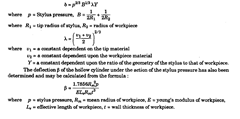
In considering the total effect of stylus
pressure, it is convenient to consider the two
effects of deformation and deflection separately.
The total error caused by the effect of stylus
pressure may be obtained by adding the deforma-
tion and deflection values together. The deforma-
tion effect is shown in Fig. 1.12. The value of the
deformation 8 may be calculated from the
relationship

Fig. 1.12. Effect of contact pressure on measurement.
1.15.9.
Errors due to looseness.
Looseness leads to errors due to penetration and
deflection. It results in inconsistent readings and inaccurate calibration. Looseness can be tested
by setting the gauge contact on gauge anvil and zeroing the meter ; and then applying finger
pressure or a light tab to each location, where looseness might be expected and noting the reading
again. It is essential for this test that the gauge anvil should be clamped down securely to gauge
frame. Metal chips or plain dirt between post and clamp can produce the pivoting effect. The gauge
contact point should be tight in the spindle.
1.15.10.
Errors due to wear in gauges.
Wear on anvils and contacts is very troublesome.
The internal instrument wear can also lead to measurement error, which can be checked by
calibration. The extent of wear hollows in anvils and lack of parallelism can be readily measured
with optical flats. The spherical contact can be checked by examination with a microscope. Wear
can be minimised by keeping gauges, masters and workpieces clean and away from dirt. Carbide
masters though wear resistant themselves, wear out hardened steel anvils. Cast-iron workpieces
present the problem of sand particles. Gauge anvil and contact materials should be properly
hardened. Chrome-plated parts have been found to withstand ten times more wear than unplated
parts.
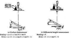
Fig. 1.13. Errors due to faulty location.
1.15.11.
Error due to location.
Fig. 1.13 shows how imperfect location of surface causes
errors and how differential measurement can reduce such errors.
1.15.12.
The Parallax Effect.
On most dials the indicating finger or pointer lies in a plane
parallel to the scale but displaced a small distance away to allow free movement of the pointer. It
is then essential to observe the pointer along a line normal to the scale, otherwise a reading error
will occur. This effect is shown in Fig. 1.14, where a dial is shown observed from three positions
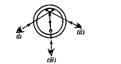
Fig. 1.14. Error due to parallax.
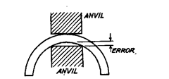
Fig. 1.15. Error due to poor contact.
where the pointer is set at zero on the scale. Observed from position (i) i.e. from the left, the pointer
appears to indicate some value to the right of zero, and from position (ii) some value slightly to the
left of zero, while only at position (Hi) with the pointer coincide with zero on the scale. Rulers and
micrometer thimbles are levelled to reduce this effect and on dials the indicators may be arranged
to lie in the same plane as the scale thus completely eliminating parallax, or a silvered reflector
may be incorporated on the scale so that the line between the eye and pointer is normal to the scale
only when the pointer obscures its own image in the reflector.
1.15.13.
Errors due to poor contact.
Fig. 1.15 shows how the poor contact of working
gauge or instrument with the workpiece causes an error. It would be appreciated that the gauge
with wide areas of contact should not be used on parts with irregular or curved surfaces.
1.15.14.
Error due to impression of measuring stylus.
Every gauge stylus has relatively
high weight. Fig. 1.16 shows how the impression of the gauge stylus indents the surface. Even a
well supported, flat bar may be difficult to measure when the gauge indents the surface on contact.
Optical or pneumatic instruments are best to avoid such error.
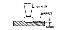
Fig. 1.16. Error due to impression of stylus on
workoiece.
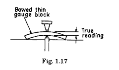
Similarly distortions due to stylus pressure occur while measuring thin walled surface.
Spring loaded gauges should be avoided and electronic/air gauges are best suited for such applica-
tions.
1.15.15.
Importance of gauging set up to be square.
Perpendicularity in gauging set
ups should be ensured properly in precision measurements as an angular error of one minute in
setting can cause 1 micron error in 100 mm. A comparator of gauge should be carefully checked for
squareness from several different angles with the gauge clamped tight. Errors of perpendicularity
may arise either due to gauge head not being set up perpendicular to workpiece or the reference
anvil on which workpiece is placed may itself be tilted.
1.15.16.
Gauging thin blocks.
For gauging thin blocks, it is advisable to use dual gauging
contact since these are liable to warp when not wrung together. Obviously enough if reading is
taken with single gauging head with bowed thin gauge block placed on surface plate, the reading
obtained will be much different, but two point gauging eliminates such problems.
