15.8.
Composite testing of gears consists in measuring the variation in centre distance when a gear is rolled in tight mesh (double flank contact) with a specified or master gear. In composite gear checking two types of checkings are made :
(a) Total Composite Variation, (6) Tooth to Tooth Composite Variation.
Total composite variation is the centre distance variation in one complete revolution of the gear being inspected ; whereas tooth to tooth composite variation is the centre distance variation as the gear is rotated through any increment of 3607JV. A uniform tooth to tooth variation shows profile variation whereas a sudden jump indicates the pitch variations.
Composite type of checking takes care of all the errors in the gears. It is specially very much suited for large gears as it also ensures control over the tooth spacing. The composite method of checking is very much suitable for checking worn gears.
Tolerance for Composite Errors.
The following table gives the tolerance on total composite errors and tooth to tooth composite error.
![]()
Master Gears.
Master gears are made with sufficient accuracy capable of being used as the basis for comparing the accuracy of other gears. These are mostly used in composite errors determination in which the master gears are rotated in close mesh (double flank) or in single contact with the gears under test. These can also be used for calibration of gear checking instruments used in shop-floor. Master gears are generally of two types i.e. Master gears type A used for checking precision gears of accuracy class upto 7 and type B master gears used for checking gears of grades from 8 to 12. Master gears are made from chromium-manganese tool steel or good quality gauge
steel and are hardened to 62 HRC. These are properly stabilised to relieve internal stresses. The master gears should preferably have lower module values because with coarse pitches the master gear would have either a very few teeth or else it will be quite big making it difficult to handle besides high-production cost.
| Class or Grade | Total Composite | Tooth or Tooth |
| of Gear | Error in Microns | Composite Errors |
| in Microns | ||
| 1 | 4 + 0.32 F | 2 + 0.16F |
| 2 | 6 + 0.30 F | 3 +0.224 F |
| 3 | 10 + 0.08 F | 4 + 0.32 F |
| 4 | 16 + 1.25 F | 6 + 0.45 F |
| 5 | 25 + 2.0 F | 9 + 0.56 F |
| 6 | 40 + 3.2 F | 12 + 0.90 F |
| 7 | 56 + 4.5 F | 16 + 1.25 F |
| CO | 71 + 5.6 F | 22+ 1.8 F |
| 9 | 90 + 7.1 F | 28 + 2.24 F |
| 10 | 112 + 9.0 F | 36 + 2.8 F |
| 11 | 140 + 11.2 F | 45 + 3.55 F |
| 12 | 180 + 14.0 F | 56 + 4.50 F |
15.8.1.
Parkinson Gear Tester.
The principle of this device is to mount a standard gear on a fixed vertical spindle and the gear to be tested on another similar spindle mounted on a sliding carriage, maintaining the gears in mesh by spring pressure. Movements of the
sliding carriage as the gears are rotated are indicated by a dial indicator, and these variations are a measure of any irregularities in the gear under test; alternatively a recorder can be fitted, in the form of a waxed circular chart and records made of the gear variation in accuracy of mesh.
Fig. 15.28 shows a gear tester for testing spur gears. (Testers are available for bevel, helical and worm gears also.)
The gears are mounted on the two mandrels, so that they are free to rotate without measurable clearance. The left spindle can be moved along the table and clamped in any desired position. The right mandrel slide
is free to move, running on steel balls, against spring pressure and it has a limited movement. The two mandrels can be adjusted so that their axial distance is equal to the designed gear
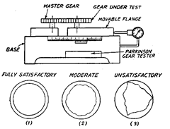
Fig. 15.28
centre distance. The spring pressure can be regulated. There are also screws for limiting the movement of the sliding carriage. A scale is attached to one carriage and a vernier to the other; this enables centre distances to be measured to within 0.025 mm. The dial indicator on the right contacts the right end of the sliding carriage and therefore indicates any radial variations of the gear under test as the gears are rotated.
When the waxed paper recorder is fitted, the chart makes a revolution for each one of the gears mounted on the sliding carriage. As the chart moves or rotates, the line traced records the movements of the floating carriage, a circle is drawn at the same time as the record. The figures shown in Fig. 15.28 are reproduction of a few typical charts with a reduced scale and the radial errors magnified about 50 times. The gear shown by No. 1 record is a fully satisfactory one, that at No. 2 is a moderate gear at No. 3 is an unsatisfactory one.
It may be noted that the method described above is dual flank method, i.e., both tooth flanks come in contact which is seldom the case in actual practice. The chart records obtained by this test do not give a clear indication of true cumulative pitch error. This test is an expedient test for accepting or rejecting a gear but not for finding out detailed causes for rejection. It is used mainly to detect poor tooth form caused by worn or inaccurate cutting tool, and pitch circle eccentricity arising from inaccurate centring of the gear blank prior to tooth cutting, etc.
Technically more correct method of mesh testing is single-flank method in which, instead of measuring centre distance variation the angular variation is measured. The mesh tester is a complex system and more costly. The simplest machine of this type consists of two shafts each carrying a gear and a plain disc having diameter equal to the nominal pitch diameter of the gear. One shaft has a rotary joint between the gear and its associated pitch disc. An indicator is used to measure angular variation between the gear and disc on this shaft. In use, the two discs are brought into frictional contact so that one can drive the other without slip. This method is not popular because it requires the manufacture of two very accurate pitch discs for every gear pair of different size. Present day’s single-flank mesh testers do not require different pitch discs. The two shafts carrying the gears are fitted with radial gratings having angular band of accurately spaced clear radial lines (one line for one minute of arc). When two such gratings (inclined at very small angle) rotate in close proximity, interference bands known as Moire fringes are formed moving in radial direction which generate electric pulses. These pulse trains are continuously phase-compared to provide a detailed chart record of gear transmission errors.
15.8.2.
Modern Gear Measuring Machines.
The surface shape of gear tooth can be defined by an equation that is linear though complex, and mechanisms can be constructed both to generate the required profile and to inspect the finished shape. In a gear testing (involute profile testing) machine, the gear is mounted on a spindle whose rotation (angular movement) can be measured by an optical grating.
A pusher touching the involute profile is mounted on a slide and moved tangentially to the base circle of the gear. According to the definition of the involute profile if the straight edge is moved at a constant linear velocity, the gear will be rotated at a constant angular velocity. Thus there is a fixed relationship between the linear velocity of the slide and the angular velocity of the gear, and by measurement and comparison of the instantaneous values of these velocities, any departure of the tooth profile from the true involute can be detected. A linear grating is used for the slide motion and a rotary grating for the gear movement. The pulse frequencies obtained from these grating systems are comparable to accuracy of the order of one part in a million. Since these two frequencies are not, in general related by a simple integral multiple, a special digital processing system is used for this purpose.
Pulses from rotary grating are fed directly to a phase comparator, and the train of pulses from linear grating are processed to convert them to the same frequency as those of the rotary grating and then fed to the phase comparator which derives the phase difference between the two inputs as an error signal which can be fed to an indicator or recorder.
15.8.3.
Measurement of Gears using Gratings.
As already mentioned, a gear could either be tested by checking involute profile, helix profile and pitch, or where faster speed of measurement is desired by method using interaction of all of above parameters, i.e., composite test (meshing gear under test with a perfectly master gear). Mechanical methods of testing demand the highest standards of mechanical accuracy which some how is limited. However with gratings, it is possible to measure large absolute angular and linear displacements to great accuracy. A big advantage of the grating is its output in the form of digital pulses which can be conveniently manipulated by digital electronic techniques.
Gear transmission errors are measured conveniently using grating as shown in Fig. 15.29.
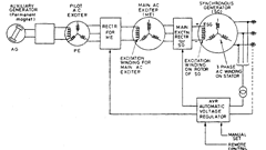
Fig. 15.29
The two gears (one to be tested and the master gear) are mounted on two shafts, each carrying a radial grating at its end. The output of the grating of driving gear is multiplied by TiT2
(where T”i = No. of teeth on gear 1, and T2 = No. of teeth on gear 2) so that the resultant output is nominally identical to that obtained from the grating fitted with the driven gear. Difference between the two signals represents the transmission error of the gear pair, in the form of a phase error. In order to improve grating accuracy, four index gratings are used and common light source feeds them via fibre optics.
Fig. 15.30 shows the principle of pitch measurement using radial grating. The signal obtained from grating is multiplied by No. of teeth (T) on the gear being tested and divided by 21,600 (No. of lines provided on the circumference of the radial grating so as to obtained a signal having a frequency which gives exactly one pulse per tooth). A small displacement transducer is mounted on a reciprocating slide in contact with the profile of gear tooth space to measure pitch error. The motion of the slide, and the moment of time at which the transducer displacement is measured, are both governed by the reference pulses derived from the grating
when the gear is stationary. The displacement transducer is inserted into a tooth space and then gear is rotated slowly. The first tooth impinges on the stylus of the transducer and produces some output. At a pre-set value, the divide circuit is initiated, and this is the starting point of the train of reference pulses. After this the transducer is withdrawn when the next tooth space is opposite the stylus, the transducer is again inserted automatically. The second tooth then deflects the stylus, and at a point determined by the second reference pulse, the intantaneous stylus deflection is measured and recorded. This provides pitch error of the second tooth, relative to the datum of first tooth. In this way pitch error of each tooth is
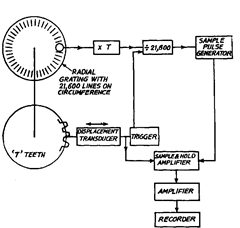
Fig. 15.30
measured. It provides direct readout of absolute indexing error and there is no need of summing up adjacent pitch errors.
For testing the gear involute profile, a radial grating is fitted concentrically on the gear shaft. A solid anvil, rigidly attached to the straight edge assembly is fitted with the tooth profile. A linear grating is installed to measure linear movement of the straight edge. As the gear is rotated, the straight edge and anvil move tangentially. The rotation of gear and movement of straight edge are thus sensed by gratings. For perfect gear tooth profile, there is a mathematical linear relationship between the two movements. The output of one of the gratings is multiplied by this linear constant and then two outputs are fed to a differential amplifier and the phase difference is fed to a recorder to indicate any error in the profile.
15.8.4.
Automatic Gear Measuring Machine.
The machine described below (Refer Fig. 15.31) is able to measure a gear more comprehensively in one automatic cycle. Gear to be tested an angle measuring system are mounted on the same shaft. For carrying out involute check, the base circle is set to an accuracy of 1 micron with the help of a digital counter by moving the setting carriage. The movement of setting carriage is measured by linear measuring system. The probe head is driven tangentially through the required length of area by the microprocessor with the linear measuring system 2 for that tangential axis having a resolution of 0.1 micron.
The horizontal carriage is driven by drive system 1 and its movement measured by linear measuring system 2. The vertical carriage with probe, mounted on horizontal carriage is driven by drive motor 1 via the steel tape operated pulley and it can move back and forth in axial direction of the gear. Provision to connect/disconnect drive to vertical column is available. The circular rotation of the component is controlled by DC drive motor 2 whose angular resolution gives a positioning accuracy of 0.5 second of arc. The microprocessor controls the relationship between the tangential movement and the angular rotation by manipulating drive motor 2 in such a way that the theoretical point of contact between the probe and the component follows
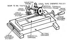
Fig. 15.31. Automatic gear measuring machine.
the true path of the involute. Variations from the perfect profile are recorded by the inductive measuring probe. Probe is made as short as possible and, at all times is kept as close as possible to the workpiece so that deflections and Abbe errors are eliminated.
For helix measurement, the vertical travel of the probe is controlled with a digital resolution of 0.1 micron. Helix angles between 0—90° can be checked. The microprocessor controls the drive 2 in such a manner that in accordance with the set helix angle, the contact point between probe and tooth flank traces a theoretically perfect helix angle and any deviations are picked up by the probe and amplified and recorded. Pitch can also be measured without changing probe. In fact same probe is used for measuring involute, lead and pitch.
15.8.5.
Gear Testing Centre
For Involute, Helix Angle and Pitch. Checks tooth flank profiles and helix angles and determines the base circle diameter or pressure angle of internal and external gears with straight and helical teeth and gear hobs. In addition, single pitch error, composite pitch error and concentricity error tests can be performed.
Fully electronic and fully automatic control devices of the test cycle replace most of the so far necessary transmission components.
An electronic travel and angle measuring system with extremely high resolution capability allows the probe to follow the trace of a perfect involute of helix angle and the path pulses that are emitted are fed directly into the computer as comparison values between true and ideal dimension.
A software programmable computer controls the entire machine cycle and performs documentation and further processing of the measuring results.
Optional add-on equipment allows automatic gear loading and unloading. This equipment includes features such as automatic probe change, automatic driver, increased cycle speed, software controlled search for tooth gaps and a CNC controlled robot for feeding and removing the gears. The computer controls the automatic cycle of the machine and robot and retrieves, lists and processes all data. A multi-colour graphic plotter with automatic paper feed produces graphic printouts.
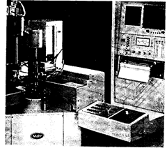
Fig. 15.32. Gear testing centre.
| Base circle dia. range | 0-550 mm |
| Max. outside dia. of gear | 600 mm |
| Module range (DP) | 0.2-20 |
| Helix angle range | 0-90° |
| Max. gear width | 150 mm |
| Additional vertical probe travel | 150 mm |
| Setting accuracy of base circle | 1 am |
| Adjustable error magnification | |
| of electronic printer | 100x, 200x, 500x, lOOOx, 2000x |
| Steady Center Attachment | |
| center distance | 20-570 mm |
| throat depth | 300 mm |
