8.9.
A clinometer is a special case of the application of spirit level. In clinometer, the spirit
level is mounted on a rotary member carried in a housing. One face of the housing forms the
base of the instrument. On the housing, there is a circular scale. The angle of inclination of
the rotary member carrying the level relative to its base can be measured by this circular scale.
The clinometer is mainly used to determine the included angle of two adjacent faces of
workpiece. Thus for this purpose, the instrument base is placed on one face and the rotary body
adjusted till zero reading of the bubble is obtained. The angle of rotation is then noted on the
circular scale against the index. A second reading is then taken in the similar manner on the
second face of workpiece. The included angle between the faces is then the difference between
the two readings.
Clinometers are also used for checking angular faces, and relief angles on large cutting
tools and milling cutter inserts.
These can also be used for setting inclinable table on jig boring machines and angular
work on grinding machines etc.
The most commonly used clinometer is of the Hilger and Watts type. The circular glass
scale is totally enclosed and is divided from 0° to 360° at 10′ intervals. Subdivision of 10′ is
possible by the use of an optical micrometer. A
coarse scale figured every 10 degrees is provided
outside the body for coarse work and approximate
angular reading. In some instruments worm and
quadrant arrangement is provided so that reading
upto 1′ is possible.
In some clinometers, there is no bubble but a
graduated circle is supported on accurate ball bear-
ings and it is so designed that when released, it
always takes up the position relative to the true
vertical. The reading is taken against the circle to
an accuracy of 1 second with the aid of vernier.
8.9.1.
Precision Microptic Clinometer.
These are used for measurement and checking of:
angular faces, gauges, relief angles on large cutting
tools, angle of milling cutter inserts, jigs and fix-
tures, levels of machine ways and bed plates, and
for setting of inclinable tables on jig boring
machines, and adjustable angle plates, angular
work on grinding and lapping machines. With the
appropriate accessories these can be used for
measuring angular displacements of small parts,
and setting out angles.

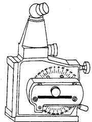
Fig. 8.27. Precision Microptic Clinometer.
The special features of precision microptic clinometer are direct reading over the range
0°—360°, optical reading system ; totally enclosed glass circles and easy-to-read scales ; main
scale and micrometer scale visible simultaneously in the eyepiece external scale for rapid
coarse setting, slow motion screw for fine setting, eyepiece rotatable to most convenient viewing
position, and hardened ground steel base.
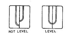
Precision Microptic Clinometer utilises bubble unit with a prismatic coincidence reader
which presents both ends of the bubble as adjacent images in a split field of view. As the vial
is levelled, the two half-images move into coincidence, making it very easy to see when the
bubble is exactly centered, without reference to any graduations. [Refer Fig. 8.28].

Fig. 8.28. Checking centering of bubble.

Fig. 8.29. Determining inclination of clinometer on scales.
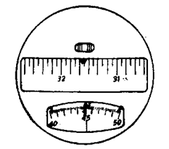
To determine the inclination of the clinometer, the bubble unit is levelled and the scales
read. On looking through the reader eyepiece, three apertures can be seen. The upper aperture
contains two pairs of double lines and two single lines. To set the micrometer, the knob is
turned until the single line is brought exactly central between the double lines. The scales can
then be read, the required angle being the sum of the readings of the main scale and the
micrometer scale. [Refer Fig. 8.29].
The double lines are imaged from one side of the circle and the single ones from a point
diametrically opposite ; by using the double lines as an index for the single line, any residual
centring error of the circle is cancelled out.
The scales are illuminated by an intergral low voltage lamp. The bubble unit is daylight
illuminated, but is also provided with a lamp for alternative illumination.
A locating face on the back allows the instrument to be used horizontally with the
accessory worktable or reflector unit.
The reference for inclination is the bubble vial. In order to measure the inclination of a
surface, the vial—to which the circle is attached is turned—until it is approximately level;
then the slow motion screw is used for a final adjustment to centre the bubble.
To measure the angle between two surfaces, the clinometer is placed on each surface in
turn and the difference in angle can be calculated.
The clinometer can be used as a precision setting tool to set a tool head or table at a
specific angle. First the micrometer scale is set and then the glass scale is rotated to bring the
relevant graduation to the index, using the slow motion screw for final adjustment. This sets
the clinometer for the required angle. Then the work surface it tilted until the bubble is exactly
centred. The work surface is thus set to the specified angle relative to a level plane.
8.9.3.
Plain Index Centre.
Index centres were actually meant for use on milling
machines, but their application has now been extended to inspection work also. This is specially
suited to those problems which involve the measurement of a large number of angular
dimensions about a common centre. The work is set between the centres and correct angular
dimensions are set directly from the indexing plate.
The index head of the centres mainly contains a crank, indexing plate, worm and worm
wheel. The crank is attached to a worm which is in mesh with a wormwheel. Three types of
indexing methods possible for obtaining a wide range of angles are simple, differential and
compound indexing.
