16.3.
16.3.1.
Levelling of the Machine.
Before the various tests on any machine tool are carried out, it is very essential that it should be installed in truly horizontal and vertical planes. In horizontal plane, both longitudinal and transverse directions are equally important. If, say, any long lathe bed is not installed truly horizontal the bed will undergo a deflection, thereby producing a simple bend and undesirable stresses will be introduced. If the bed is not installed truly horizontal in transverse direction, twist will be introduced. Thus the movement of the saddal can’t be in a straight line and true geometric cylinder can’t be generated.
For proper installation and maintenance of its accuracy, a special concrete foundation of considerable depth must be prepared. Also this must be insulated from the surrounding floor by introducing some form of damping.
The level of the machine bed in longitudinal and transverse directions is generally tested by a sensitive spirit level. The saddle is kept approximately in the centre of the bed support
feet. The spirit level is then placed at a-a (Fig. 16.1), the ensure the level in the longitudinal direction. It is then traversed along the length of bed and readings at various places noted down. For test in transverse direction the level is placed on a bridge piece to span the front and rear guideways and then reading is noted. It is preferable to take two readings in lon-
gitudinal and transverse directions simultaneously so that the effect of adjustments in one direction may also be observed in the other. The readings in transverse direction reveal any
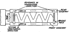
Fig. 16.1
twist or wind in the bed. It may be noted that the two guideways may be perfectly levelled in longitudinal direction, but might not be parallel to each other. This is revealed by the test in transverse direction.
The straightness of bed in longitudinal direction for the long beds can also be determined by other methods, e.g., using straight edges, autocollimators or by taut wire method. But the test in transverse direction can be carried out only by spirit level.
It is desired that the front guideway should be convex only as the cutting forces and the weight of carriage act downward on it. If the front guideways are concave, then the effect will be comulative. The tendency of the carriage, under cutting forces is to lift upwards from the rear and this is prevented by a gib placed underneath the guideways. With the result, an upward force acts on the rear guideways ; which must, therefore, be made concave.
Transverse level may be in any direction, but no twist can be tolerated.
16.3.2.
True Running of Locating Cylinder of Main Spindle.
Locating cylinder is provided to locate the chuck or face plate. However locating surface can’t be threaded one as threads get worn out soon and thus introducing play in face plate or chuck. Thus locating surface is cylindrical and this must run truly; for only then the face plate etc., can run truly. The dial indicator is fixed to the carriage (or any other fixed member) and the feeler of the indicator touches the locating surface. The surface is then rotated on its axis and indictor should not show any movement of needle.
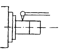
Fig. 16.2
16.3.3.
Axial Slip of Main Spindle and True Running of Shoulder Face of Spindle Nose.
Let us first distinguish between the axial play and the axial slip. Axial play means the indispensable freedom of spindle movement in axial direction to prevent it from
seizing by heating. The spindle is supported between two bearings. Due to running of spindle, there will be a rise in temperature and thermal expansion of spindle would be there. If no axial play is allowed, it would try to bend. Thus there will be no adverse effect of axial play if the direction of cutting forces remains same. If the direction of cutting force changes, there would be some error introduced due to movement of spindle axially in either direction. Under such conditions, therefore, it is advisable to cut threads in one direction only.
Axial slip is defined as the axial spindle movement which
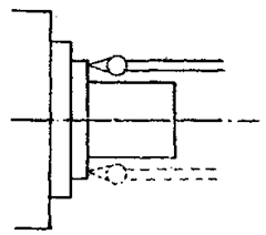
Fig. 16.3
follows the same pattern and is due to the manufacturing error. Actually this test is meant to check this error. To test this the feeler of the dial gauge rests on the face of the locating spindle shoulder and the dial gauge holder is clamped to the bed (Fig. 16.3). The locating cylinder is then rotated and the change in reading noted down. The readings are taken at two diametrically opposite points. The total error indicated by the movement of the pointer includes three main sources of errors.
(i) Axial slip due to error in bearings supporting the locating shoulder, i.e., the bearings are not perpendicular to the axis of rotation and due to it a point on the shoulder will move axially in and out at diametrically opposite points.
(ii) Face of the locating shoulder not in a plane perpendicular to axis of rotation. (Hi) Irregularities of front face.
Due to axial slip, in screw cutting, the pitch will not be uniform due to periodic movement of the spindle. This, however, is not important while turning.
16.3.4.
True Running of Headstock Centre.
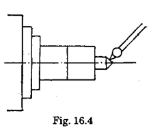
Headstock centre is live centre and the workpiece has to rotate with this centre. If it is not true with the axis of movement of the spindle, eccentricity will be caused while turning a work, as the job axis would not coincide with the axis of rotation of main spindle. For testing this error, the feeler of the dial indicator is pressed perpendicular to the taper surface of the centre (Fig. 16.4), and the spindle is rotated. The deviation indicated by the dial gauge gives the trueness of the centre.
16.3.5.
Parallelism of the Main Spindle to Saddle Movement.
This has to be checked in both vertical and horizontal planes. In this we require the use of mandrel. An important precaution in the use of mandrels and dial indicator is mentioned here. The mandrel must be so proportioned that its overhang does not produce appreciable sag, or else the sag must be calculated and accounted for. The rigidity indicator set up is also very important and must be carefully watched. Otherwise variations in readings are recorded by pointer may be solely due to deflection of the indicator mounting in different positions and it becomes very difficult to detect and isolate the spurious deflection from the true variations.
If axis of the spindle is not parallel to bed in horizontal direction, a tapered surface is produced.
Any deviation from parallelism of spindle axis from bed in vertical axis will produce a hyperboloid surface. For this test, a mandrel is fitted in the taper socket of the spindle. Mandrel has a concentric taper shank which is close fit to the spindle nose taper. The feeler of the dial indicator is pressed on the mandrel and the carriage is moved. The indication in horizontal plane is given by dial (b) and in vertical plane by dial (a) (Fig. 16.5). In vertical plane the mandrel should be rising towards

Fig. 16.5
the free end in order to counteract the weight of mandrel and job. But for counter-acting cutting forces, it should be lower towards free end. In horizontal plane, mandrel should be inclined in a direction opposite to the direction of tool pressure.
16.3.6.
True running of taper socket in main spindle.
If the axis of tapered hole of the socket is not concentric with the main spindle axis, eccentric and tapered jobs will be produced. To test it, a mandrel is fitted into the tapered hole and readings at two extremes of the mandrel are taken by means of a dial indicator as shown in Fie. 16.6.

Fig. 16.6
16.3.7.
Parallelism of tailstock guideways with the movement of carriage.
Sometimes the job is held between head-stock and tail stock centre for turning. In that case the job axis must coincide with the tailstock centre. If the tailstock guideways are not parallel with the carriage movement there will be some offset of the tailstock centre and this results in taper turning.
To check the parallelism of tailstock mideways in both the planes i.e., horizontal and vertical, a block is placed on the guideways as shown in Fig. 16.7 and the feeler of the indicator is touched on the horizontal and vertical surfaces of the block. The dial indicator is held in the carriage and carriage is moved. Any error is indicted by the pointer of dial indicator.
16.3.8.
Movement of upper slide parallel with main spindle in vertical plane.
The dial indicator if fixed in the tool post. A mandrel is fitted in the spindle. The feeler
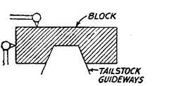
Fig. 16.7
of the dial gauge is pressed against the mandrel in vertical plane and the upper slide is moved longitudinally. This error is not tested in horizontal plane because there is swivelling arrangement for taper turning.
Parallelism of tailstock sleeve to saddle movement. If the tailstock sleeve is not parallel to the saddle movement, the height of dead centre would vary as varying lengths of sleeve are taken out. For the jobs held between two centres, it is necessary that the central axis of the dead centre be coaxial with the job axis in both the planes. If it is not so, the job

may be tilted up or down or in sideways due to the support of the dead centre. The test is carried out by fixing the dial indicator on the tool post and pressing the plunger against the sleeves first in vertical and then in horizontal plane (Fig. 16.9). The carriage is moved along the full length of the sleeve and deviations as indicated by dial indicator are noted down. Tailstock sleeve should be rising towards the free end in vertical plane and should be inclined towards the tool pressure in horizontal plane.
16.3.10.
Parallelism of tailstock sleeve taper socket to saddle movement.
A mandrel is put in the sleeve socket. The dial gauge is fixed on the tool post and plunger is pressed against the mandrel
and saddle is moved from one side to the other. This test is carried out in both the horizontal and vertical planes.
16.3.11.
Alignment of both the centres in vertical plane.
Besides testing the parallelism of the axes individually (main spindle axis and tailstock axis) it is-necessary to check the relative position of the axes also. Both the axes may be parallel to carriage movement but they may not be coinciding. So when a job

Fig. 16.10
is fitted between the centres, the axis of the job will not be parallel to the carriage movement. This test is to be carried out in vertical plane only. A mandrel is fitted between the two centres and dial gauge on the carriage. The feeler of the dial gauge is pressed against the mandrel in vertical plane as

Fig. 16.11
shown in Fig. 16.11 and the carriage is moved and the error noted down.
16.3.12.
Pitch accuracy of lead screw.
The accuracy of the threads cut on any machine depends upon the accuracy of its lead screw. Thus it is very essential that pitch of the lead screw throughout its length be uniform.
Test for this is performed by fixing a positive stop on the lathe bed. Against the stop, the length bars and slip gauges can be located. An indicator is mounted on the carriage and first it makes contact against the calculated length of slip gauges. The initial loading of the dial gauge against the slip gauge is noted. The slip gauges are then removed and the carriage is connected to the lead screw and lead screw is disconnected from the gear train. An indexing arrangement is utilised for rotating the lead screw and lead screw is given some revolutions so that distance travelled by carriage is equal to the length of slip gauges. The reading of the dial indicator against the stop is noted down in this position. It it is same as before, there is no error, otherwise it can be recorded. In this method, care must be taken not to disturb the datum location when changing the gauges for testing different pitch lengths.
A suitable method for recording the progressive and periodic errors is by using a suitably divided scale, which is placed close to the line of centres. A microscope is rigidly mounted on the carriage in a convenient position to note the readings on the scale.
16.3.13.
Alignment of lead screw bearings with respect to each other.
The alignment of the bearings decides the position of the lead screw. Misalignment of lead screw i.e., it not being parallel to the bed in vertical plane or horizontal plane can cause additional stresses due to bending, when carriage is moved. Due to it the lead screw might get damaged and the precision of the machine is reduced :
Alignment of lead screw bearing with split nut in both the planes is also essential.
16.3.14.
Axial slip of lead screw.
The thrust face and the collars of the lead screw (or the abuttment collar and the thrust bearing of the screw) must be exactly square to the screw axis, otherwise a cyclic endwise movement is set up which is of the same nature as the axial slip in the main spindle. Thus a periodic pitch error will be additional to any true periodic errors in the pitch of the screw.
For testing the axial slip in lead screw, a ball is fitted in the end of lead screw and the feeler of the dial gauge is pressed against the ball. The lead screw is rotated and deviation, if any, in any direction is noted down (Fig. 16.12).

Fig. 16.12
16.3.15.
Practical tests.
These tests consist of the actual turning of some jobs on the machine. The job is made under prescribed condition of cutting speed, feed and depth of cut. The test piece is then measured for its geometry and surface finish and results compared with the standards as prescribed by the manufacturer. These tests are designed to reveal the combined effects of possible errors in alignment accuracy and the rigidity of machine.
The various jobs to be made as prescribed by M/s Hindustan Machine Tools are given
below.
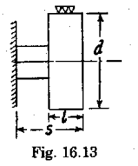
(i) Working accuracy of machine of cylindrical turning (chucking). S’ should be as small as possible.
Permissible error = 0.01 mm.
| Swing over bed ‘mm* | d mm | / mm |
| upto 300 | 50 | 10 |
| over 300 and upto 500 | 80 | 15 |
| Over 500 | 120 | 20 |
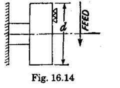
(ii) Working accuracy of machine facing : Permissible error=0.02 mm over the diameter of test workpiece, which is taken as 300 mm for swing over bed of upto 500 mm, and 400 mm for swing over 500 mm.
(Hi) Working accuracy of cylindrical turning, the job held between centres.
D = L/8 max.
L = half to full centre distance. Permissible error is 0.02 mm/300 mm.
