ABSTRACT
A series of cyclic loading nanoindentation experiments with varied maximum loads (Fmax) of 0.05 to 2.0 mN were performed on a nanostructured, layered muscovite with loading direction normal to its basal plane. A critical load (e.g., 0.5 mN) exists that leads to distinct load-displacement curves: when Fmax is greater than this load, the loading/unloading curves, after a few initial cycles, become characteristic closed hysteresis loops, suggesting that shakedown process occur quickly; otherwise, only nonlinear elastic, completely overlapped hysteresis loops were observed. These phenomena result in two representative elastic moduli that depend on indentation depth. For Fmax (e.g., 0.05 and 0.1 mN) smaller than the critical load, the obtained elastic modulus at the nonlinear elastic state is nearly 88 GPa, which agrees with the reported Young’s modulus of the material; However, when Fmax exceeds the critical value, the measured modulus decreased to a lower constant value around 55 GPa, close to the bulk modulus of muscovite. The transition from a higher, true Young’s modulus to a lower bulk modulus can be attributed to the three dimensional confinement around the indenter tip after plastic shakedown at relatively larger depth, where significant alteration to the originally layered structure of muscovite has taken place.
INTRODUCTION
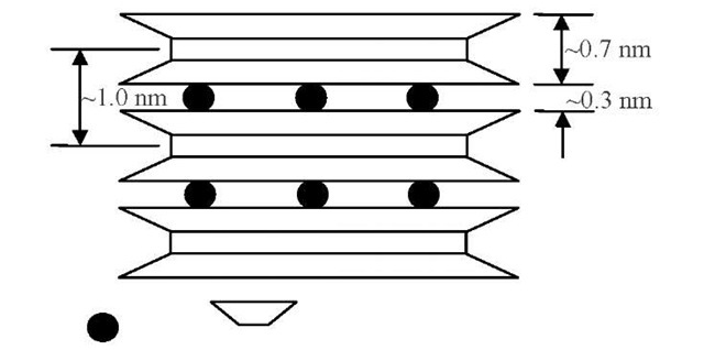
Phyllosilicate minerals, major constituents of soils and rocks, are ubiquitous in the Earth’s crust. They consist of either discrete or mixed-layered sequences of fundamental, continuous 1:1 or 2:1 layers of 0.7 or 1.0 nm in thickness, respectively, with distinct sub-nanometer thick interlayers, thus phyllosilicates can be treated as naturally occurring nanostructured layered materials. These materials are usually platy in shape with high aspect ratios (e.g., diameter to thickness ratio ranges from 10:1 to 100:1). Their platy morphology and complex layered structure render them significant anisotropic properties and make it difficult to measure the elastic and plastic properties. For instance, the Young’s moduli at different directions (e.g., directions perpendicular to (001) or (010) plane) are expected to vary significantly. In nature, some of these materials (e.g., mica) occur as macrocrystals, thus rendering them a suitable analog material for the study of nanomechanics of synthesized or manufactured nanostructured multilayers [1-5]; while others may exist as micro to nano crystallites, and the measurement of their bulk modulus is a difficult, challenging task. Further, accurate determination and better understanding of their mechanical properties are of essential relevance to geomechanics, geophysics, and other disciplines related to subsurface explorations and the design and construction of foundations to civil infrastructure.
Muscovite is a non-expandable dioctahedral 2:1 phyllosilicate mineral with an ideal crystal formula K(Si3Al)Al2Oio(OH)2 [6], Its 2:1 layers typically possess a negative layer charge of -1.0 per Oio(OH)2 unit, which are balanced by non-hydrated or unsolvated interlayer K+ cations that tightly hold adjacent layers together. Figure 1 shows a schematic illustration of the crystal structure of muscovite. The interlayer bond can affect the material’s compressibility significantly, as further elaborated below.
Fig. 1 Schematic illustration of the ideal crystal structure of muscovite
The isothermal bulk modulus of muscovite was experimentally examined by isotropic compression testing. Comodi and Zanazzi [7] studied the high-pressure structural variations and compressibility of both K-muscovite and Na-muscovite and observed that the bulk moduli of these two muscovites are 49 and 54 GPa (±3 GPa), respectively. They further pointed out that the smaller bulk modulus of K-muscovite when compared with Na-muscovite is due to the higher compressibility along the [001] direction and higher compressibility of the K-0 bonds in the interlayer region. These results also agree with the compressibility data (i.e., 56 GPa) of Catti et al. [8] obtained on 2M\ K-muscovite sample using powder neutron diffraction at room temperature. Other Brillouin scattering measurements, which can examine the 13 independent elastic moduli of monoclinic crystals, have also shown that the elastic modulus of muscovite along the oaxis is about 58.6 [9] or 61 GPa [10], Sekine et al. [11] used a shock-wave equation of state to estimate the bulk modulus of natural muscovite sample, which is 52 GPa. All these modulus values are statistically identical, given that the examined samples may vary in chemical composition and crystal structure.
Prior research has also found that muscovite exhibits interesting and distinct mechanical behavior under nanoindentation. For example, Barsoum et al. [12] observed the occurrence of fully reversible, superimposed stress-strain hysteresis loops when a muscovite single crystal was subjected to indentation repeated loading under a spherical indenter, and attributed the nonlinear elastic hysteresis loop to the formation and annihilation of incipient kink bands (IKBs). They further pointed out that muscovite and other layered minerals and materials (e.g., graphite, layered ceramics) belong to a group of kinking nonlinear elastic solids. Zhang et al. [13,14] observed that the elastic modulus of muscovite exhibits an apparent indentation size effect (ISE) based on a series of nanoindentation experiments conducted with a sharp Berkovich indenter. Furthermore, this kind of ISE, or in other words, the decrease in the measured elastic modulus with increasing indentation depth, is not typically observed for metals or other stereotypical crystalline materials. Yin and Zhang [15] examined the nanoindentation behavior of muscovite subjected to repeated loading. They found that a critical maximum load exists, which marks the material’s completely different responses to repeated loading, resulting in different values of elastic modulus.
This paper aims to investigate the influence of cyclic nanoindentation shakedown observed on muscovite under repeated loading on the estimation of its elastic moduli, including both Young’s modulus and bulk modulus. Following the conclusions in Yin and Zhang [15], this paper further extends the experimental observations and discusses the transition of the measured Young’s modulus along the [001]* direction to the bulk modulus. If cyclic nanoindentation shakedown occurs, a smaller stiffness along the [001]* direction results from a large number of loading/unloading cycles. A particular focus is on the influence of load level on the nanoscale deformation of this mineral under cyclic nanoindentation loading and the resulting change in elastic modulus. It is hoped that the experimentally derived phenomenological behavior can help future analytical work to establish a more theoretical understanding of the aforementioned transition of the elastic modulus.
SAMPLE PREPARATION
The muscovite sample chosen for this study was collected from Panasqueira, Portugal. Its chemical composition and crystal structure were well analyzed previously [16]. It is a 2M1 mica polytype and has a layer charge of -1.05 with a chemical formula (K1.00Na0.03Ca0.01)(Al1.93Fe2+0.01Mg0.01Mn0.01)(Si3.09Al0.91)O10(OH)1.8sF0.12. A carefully selected small fragment with an in-plane dimension of > 2 mm and a thickness of > 0.1 mm was gently cleaved off the muscovite rock chip and then used for subsequent sample mounting.
A piece of single-crystal silicon wafer (100) (MTI Corporation, Richmond, CA) with a dimension of 10 x 10 x 0.6 mm (length x width x thickness) was used as substrate that provides atomically flat surface for sample mounting. A regular aluminum puck was first heated to 130 oC on a hot plate and then a thin layer of Crystalbond 509 amber resin (Aremco Products, Inc., New York), which melts at a temperature of 130 oC or higher, was applied to the puck surface. This was followed by carefully placing the silicon wafer substrate onto the puck surface where the resin was applied. To avoid trapping air between the resin and wafer interface, the wafer was gently pressed into the melted resin with a continuous rotation along one straight edge. Sufficient time was allowed for the wafer to be heated to 130 oC. Then another thin layer of amber resin was applied onto the silicon wafer surface, followed by carefully placing the muscovite sample onto the silicon wafer in a similar manor. Moreover, to prevent overheating the muscovite sample, immediately after the sample placement, the entire sample set (i.e., including alumina puck, silicon wafer, and muscovite) was removed off the hotplate to a leveling table for cooling. Finally, a very thin layer was cleaved off top of the muscovite sample with a razor blade so that a fresh and intact surface was exposed for nanoindentation loading.
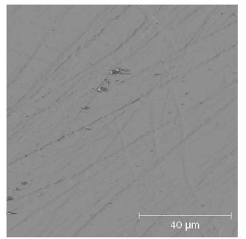
Before indentation testing, the sample was first examined under an optical microscope to check the sample dimension and quality of sample mounting. No cracks are observed within the sample, indicating that this fragment is most likely a single crystal. The surface topography of the sample was further characterized using an Agilent 5500 atomic force microscope (AFM) (Agilent Technologies, Inc., Chandler, AZ). Figure 2 shows a typical AFM micrograph for an area of 100 x 100 m on the muscovite surface. It is normal that an air-cleaved mica may not yield atomically flat surface due to surface contamination by the atmosphere and the reaction of interlayer K+ with atmospheric water and CO2 [17]. The blurred lines, divided into several parallel sets, are either very tiny scratches caused by a cotton swap during sample surface cleaning or the edge and screw dislocations that are previously present in the crystal or newly introduced by cleaving [18-20]. Again, no cracks are observed in the scanned area.
Fig. 2 The surface topography of the tested muscovite fragment (AFM image)
NANOINDENTATION TESTING
An MTS Nano XP indenter (MTS Nano Instruments, Inc., Oak Ridge, TN) was employed for all nanoindentation experiments. Totally six tests, which used two different loading methods including the MTS standard method, and the cyclic loading method modified from the MTS standard method, were performed with a dynamic contact module (DCM) head equipped with a diamond Berkovich tip of < 20 nm in tip radius. The DCM head has a load resolution of 1.0 nN and displacement resolution of < 0.01 nm. For each test, typically 2-9 duplicate indents at a spacing of 100 ^m were performed to ensure measurement repeatability. All tests were run with an allowed thermal drift rate of < 0.05 nm/s.
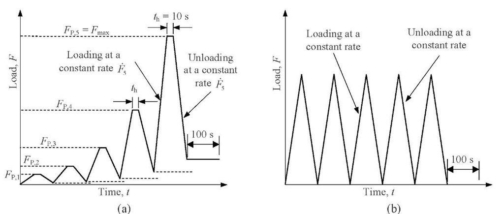
Fig. 3 The loading profile for (a) the MTS standard method and (b) cyclic loading method modified form the MTS standard method
The MTS standard method applies indentation load at a constant loading rate under load control mode. Figure 3 a depicts the loading sequences for this method. The maximum load (Fmax) and loading time (tL) were preset to 2.0 mN and 30 s, respectively. It takes 5 cycles of loading and unloading (L/U) to reach the Fmax. For the i-th cycle (where i = 1, 2, …, 5), the peak load FP,i and loading rate to peak load F are given by
where N is the total number of L/U cycles or 5 for this test. For the unloading section of each cycle, the unloading rate was kept the same as that of loading section of that same cycle, and the load was reduced to the 90% of the peak load of that cycle. Also, at the peak load, a holding time (Th) of 10 s was allowed in all L/U cycles. At the end of the 5th cycle unloading, a holding time of 100 s was allowed for thermal drift correction.
The MTS standard method was modified to perform cyclic loading tests (Figure 3b). Three modifications were made, including keeping the peak load of each cycle the same as the Fmax, reducing the holding time to zero at all peak loads, and changing the percentage of unloading from 90% in the MTS standard method to 100% in the repeated loading method. All other parameters remained the same. Totally 5 tests with different Fmax and loading time tL were performed.
ANALYSES OF RESULTS
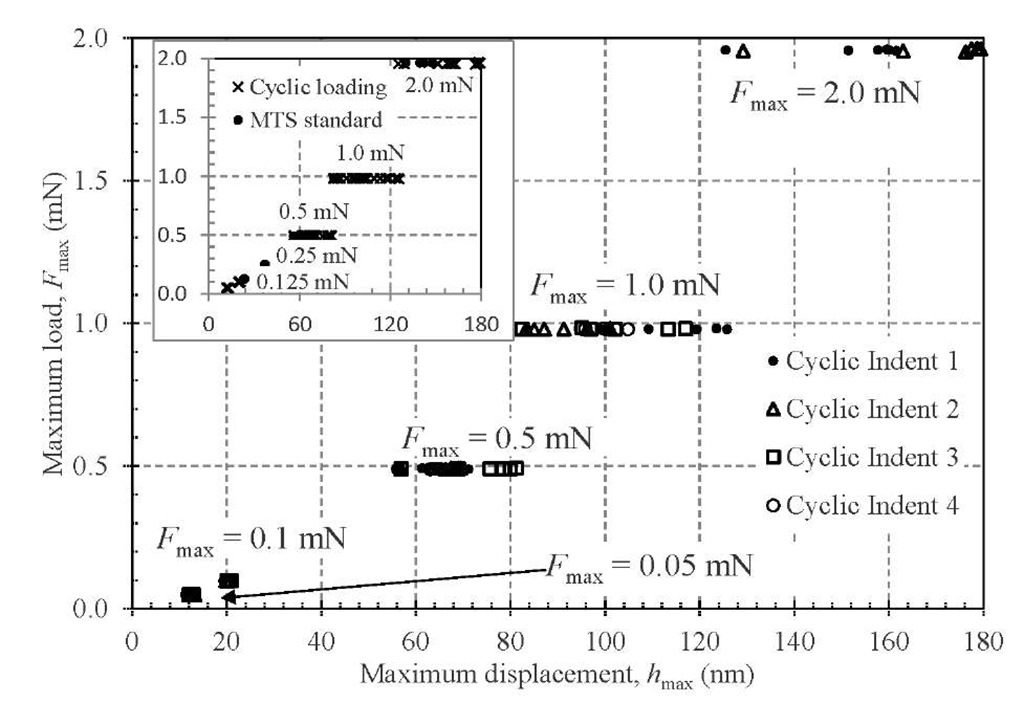
Fig. 4 The relationship between maximum load and maximum displacement for all cyclic loading tests
Figure 4 collectively summarizes the relationship between the Fmax and maximum indentation depth Hmax for all tests performed under cyclic loading, including the one by the MTS standard method (see inset).
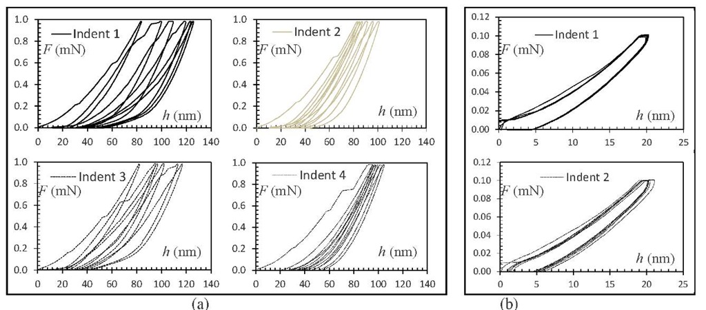
It is clearly shown that the data points can be categorized into two groups according to the Fmax: (1) When Fmax < 0.25 mN, superimposed points are observed, indicating that the hmax remains the same in spite of multiple L/U cycles; (2) When Fmax > 0.5 mN, the data points at a given Fmax are scattered over a wide band whose width increases with the Fmax. The observed data scattering is attributed to the pop-ins whose accumulative extension usually increases with Fmax [15]. Figure 5 illustrates how pop-ins affect the indentation depth with two representative tests at Fmax = 1.0 and 0.1 mN. Pop-ins of varying extensions occur randomly in the first few loading sections of the L/U cycles when the Fmax exceeds the critical value (Figure 5a). With these pop-ins, the L/U hysteresis loops start to disperse and move toward the right side. After a few cycles, the L/U loops tend to converge to a stabilized one, and this phenomenon is named "shakedown" [21-23]. It refers to the process, under repeated loading, whereby the plastic deformation caused by initial L/U cycles introduces a system of residual protective stresses which make the steady cyclic state purely elastic [22] or cyclically plastic [23], leading to elastic shakedown or plastic shakedown, respectively [23]. During the process of shakedown, the occurring frequency and extension of the pop-ins also tend to decrease and even disappear with the number of L/U cycles increasing. This also suggests that pop-ins be the major cause of non-recoverable or permanent deformation during nanoindentation loading for the tested mineral. This phenomenon is in accordance with the observed increase of the L/U loop width and of the pop-ins number or occurring frequency.
Fig. 5 The load-displacement curves of Tests performed under cyclic loading
The occurrence of random pop-ins and accordingly shakedown behavior of the tested muscovite can lead to significant variation in elastic modulus E, if the accumulative hmax is used to estimate the projected contact area and contact stiffness by following the Oliver and Pharr [24,25] method. Further details can be found in Yin and Zhang [15]. Because the loading direction is normal to the basal plane of the phyllosilicate mineral, the derived elastic modulus is referred to the [001] direction.
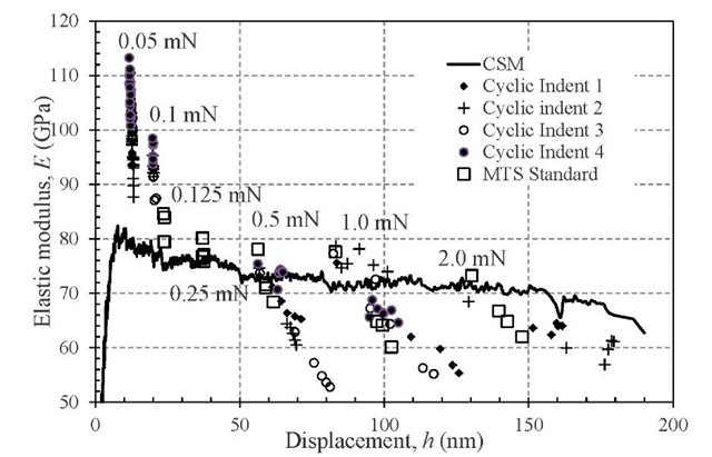
Figure 6 summarizes the elastic modulus obtained from all tests. As a reference, the continuous E-h curve obtained by the continuous stiffness measurement (CSM) method [15] is also shown here. For smaller Fmax (i.e., < 0.25 mN), the E values obtained by the repeated loading method lie above the continuous E-h curve by the CSM method. For higher Fmax (i.e., > 0.5 mN), the majority of the E values lie below the continuous curve. Moreover, for a given large Fmax (> 0.5 mN), the E values fall inside a scattered band and decreased significantly with indentation depth. Overall, the derived elastic modulus values range widely from 55 to 115 GPa, indicating that the apparent indentation size effect exists for this mineral’s Young’s modulus. Furthermore, the E values decrease significantly during the first few L/U cycles and quickly stabilize to a single value, which agrees with the observed overlapped L/U loops very well. Another important feature is that at the same Fmax for cyclic loading, the E values also decrease with the number of L/U cycles, leading to two different characteristic points:
• When Fmax > 0.5 mN, the measured elastic modulus at the final shakedowned cycles is around 55 GPa, and this value agrees very well with the reported bulk modulus of muscovite, which ranges from 49 to 62 GPa. It should be noted that, although the derived elastic moduli at the final shakedowned cycles are around 55 GPa, some variations exist for this value, e.g., 70 GPa for Indent 2 and 65 GPa for Indent 3 at Fmax = 1.0 mN. According to the general relationship between an isotropic material’s Young’s modulus (E) and bulk modulus (K): E = 3K(1-2v)), if the Poison’s ratio (v) of the muscovite is 0.25 [26] and the above bulk modulus of 55 GPa is used, then the E value is 83 GPa,
• When Fmax < 0.25 mN, the derived elastic modulus after 20 L/U cycles is around 88 GPa, which is close to the E value (83 GPa) estimated based on the bulk modulus.
Fig. 6 The elastic modulus of the muscovite derived from all tests
DISCUSSION
The nanostructured layered muscovite exhibits, when subjected to cyclic nanoindentation loading, multiple modes of complex nanoscale deformation in response to different levels of load. A critical load exists that leads to distinctly different load-displacement curves: when Fmax is greater than this load, the observed curves exhibit characteristic closed hysteresis loops, after a few initial loading/unloading cycles, suggesting that shakedown process occur quickly in muscovite; otherwise, only nonlinear elastic, completely overlapped hysteresis loops were observed. These phenomena lead to two representative elastic moduli that depend on indentation load or depth. At smaller Fmax (e.g., 0.05 and 0.1 mN), the obtained elastic modulus at the nonlinear elastic cyclic loops was nearly 88 GPa, which agrees with the reported Young’s modulus, ranging from 79-84 GPa [13,27]; However, when the Fmax exceeds the critical value (e.g., >0.5 mN), the measured elastic modulus decreased to a lower value around 55 GPa, close to the bulk modulus of muscovite. This transition from a higher Young’s modulus obtained from smaller indentation load to a lower bulk modulus obtained from larger indentation load can be attributed to the three dimensional confinement around the indenter tip at a relatively larger depth, where significant alteration to the original layered structure of muscovite has taken place. The alteration to the layered structure, as reflected by the cyclic plastic shakedown, leads to changes in the elastic behavior of the material in the region affected by the cyclic indentation loading. In general, three mechanisms contribute to this phenomenon: the protective residual stress induced by plastic deformation of prior L/U cycles; the increased contact area along with accumulated plastic deformation, leading to reduced contact stress (even though the indentation load remains the same); and the strain-hardening of the material. For the tested muscovite, the former two mechanisms may be dominant. During the process of shakedown, the occurring frequency and extension of the pop-ins tend to decrease and even disappear, resulting in non-recoverable or permanent deformation for the tested layered material. Similar phenomena have also been reported on mica and other layered materials (e.g., Ti3SiC2)[12,28].
Fig. 7 Schematic of the nanoscale modes of deformation at (a) small maximum load where only IKBs but no plastic deformation occurs; and (b) large maximum load where layer delamination and basal plane rupture take place
As pointed out by Comodi and Zanazzi [7], the compressibility of anisotropic K-muscovite is highly dependent upon the compressibility of dioctahedral layer and the strength of interlayer K-O bond. The layer structure also results in the nonlinear kinking elastic deformation, resulting from the incipient kink bands (IKBs), when the indentation load is relatively small (Figure 7a). Therefore, the Young’s modulus of the [001]* direction, as obtained from the cyclic loading indentation under smaller Fmax, is affected by the kinking elastic deformation. Whether this modulus reflects the true Young’s modulus or the definition of the traditional Young’s modulus should include nonlinear kinking elasticity needs further investigation. When the Fmax is greater than the critical load, after certain cycles of loading/unloading, the initially generated IKBs are forced to separate from each other and move away from the indenter tip, resulting in the formation of kink bands. The movement of kink boundaries can further result in the delamination and even rupture of basal planes [29]. Once the layer delamination occurs, significant alteration to the original layered structure of muscovite has taken place, leading to the rearrangement of the muscovite layers around the indenter tip, just like a 3-D confinement of the tip at a greater depth (Figure 7b). Therefore, the elastic indentation unloading is very similar to the 3-D unloading, and the derived Young’s modulus based on the indentation unloading approximates the bulk modulus.
CONCLUSIONS
This study has examined the elastic moduli of muscovite derived from cyclic nanoindentation loading at [001]* direction. The maximum indentation load affects the mineral’s response to cyclic loading, resulting in two different elastic moduli that correspond to the nonlinear kinking elasticity and the cyclic plastic shakedown. These nanoscale modes of deformation are closely related by the intrinsic layered structure of muscovite. In particular, the following conclusions can be drawn:
(1) The elastic modulus, 88 GPa, obtained from the nonlinear kinking elastic hysteresis loops is close to the Young’s modulus. However, whether this value is the true Young’s modulus needs further research;
(2) The elastic modulus, 55 GPa, obtained at the cyclic plastic shakedown stage approaches the bulk modulus. This is caused by the layer delamination and basal plane rupture, accompanied by the 3-D confinement of the indenter tip at a larger depth (under a larger load).
(3) The reported experimental observation may lead to the development of a cyclic nanoindentation technique for determining the bulk modulus of certain materials with layered structure that are prone to plastic shakedown when subjected to cyclic loading.
