Abstract
Metamaterials are devices with embedded structures that provide the device with unique properties. Several applications for metamaterials have been proposed including electromagnetic cloaks, lenses with improved resolution over traditional lenses, and improved antennas. This research addresses an obstacle to practical metamaterial development, namely the small bandwidth of current metamaterial devices. This research characterizes the effectiveness of several metamaterial designs. The basic design incorporates a microelectromechanical systems (MEMS) variable capacitor into a double negative (DNG) metamaterial structure. One set of devices is fabricated with the MEMS capacitor in the gap of the split ring resonator (SRR) of the DNG metamaterial. Applying voltage to the MEMS device changes the effective capacitance, thereby adjusting the resonant frequency of the device. Additionally, similar devices with three possible capacitor layouts are examined with stripline measurements and computer models. Recommendations for design improvements are provided. The initial capacitor layout with MEMS capacitors in the split ring gaps is recommended for future design iterations with adjusted gap capacitance values.
Introduction
Metamaterial devices have received much attention over the past two decades. There are many definitions for metamaterials. For this research effort, a metamaterial is defined as an "arrangement of artificial structural elements designed to achieve advantageous and unusual properties" [1]. In spite of the attention garnered by metamaterials, the science behind their apparent unusual properties is not settled.
According to some researchers, metamaterials can be viewed to have a set of macro effective parameters for the medium, much as a molecular lattice interacts with incident electromagnetic fields. These effective constituent parameters produce quantities such as the effective index of refraction and effective impedance. These quantities dictate the behavior of the electromagnetic fields inside a metamaterial and are what gives a metamaterial its unusual properties.
The effective permittivity and permeability are controlled by the geometry of the structural building blocks, the unit cells. When both the permittivity and permeability are negative, the material is referred to as a double negative (DNG) material and takes on a negative index of refraction [7]. Commonly, DNG materials are constructed with wire lattices and a pair of split ring resonator (SRR) particles. The unique properties associated with DNG materials are limited to the resonance regions of the metamaterial devices.
Previous research has shown a myriad of ways to adjust the dispersive resonance region of metamaterial devices. The metamaterial designs in [3] and [4] depend on the inclusion of tunable magnetic and dielectric material respectively to adjust the resonant frequency. In [5], the authors propose a design that employs a varactor diode to adjust the resonant frequency; however the varactor is large, leading to a perturbation of the pure SRR and complicating structure scalability for manufacturing. The authors in [6] and [7] present a similar design with alternate placements of the varactor. This diode is controlled by the incident electric field, automatically adjusting based on the incident power. Similar to the design examined in this paper, the structures in [8] use a MEMS device to control the resonance of an SRR particle, but their MEMS device is a switch, not a variable capacitor. The authors of [9] present an alternate structure with series capacitors that are controlled with a static electric field, which is similar to the method used to control the capacitance of the metamaterial presented in this paper, however, their capacitance changes are based on changes to the permittivity of the dielectric present. The metamaterial design analyzed in this paper uses a microelectromechanical systems (MEMS) variable capacitor that has six distinct states. It has a small footprint that is fabricated as part of the SRR element and is independent of the incident electromagnetic field. Based on the work of Lundell in [10], the intra-ring capacitance is expected to have a greater impact than the gap capacitance with the larger structures. Variants of the proposed structure with different MEMS capacitor layouts are examined using computational and measurement techniques.
Theory
The devices analyzed in this paper attempt to adjust the resonant frequency of the metamaterial device by including an additional circuit element in the equivalent circuit model of the structure. Using the equivalent circuit model, the particle’s resonant angular frequency is given in the microwave frequency regime by [8]
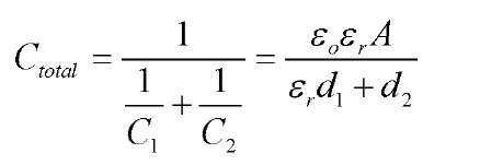
The capacitance (Ceq) and inductance (Leq) of an SRR is dependent on the material it is made of as well as its dimension and shape. A novel metamaterial structure that achieves frequency adaptability was proposed in a previous research effort [11]. The structure is based on a basic DNG unit cell. The proposed structure also incorporates a MEMS variable capacitor across the gaps of the SRR particles. Fig. 1 shows the proposed initial design layout. The presence of the cantilever beams on the SRR creates a new source of capacitance which modifies the resonance of the structure. The cantilever beams are pulled down by applying voltage to the cantilever control lines. With no voltage applied, all of the cantilever beams are in the up state. With all the beams raised, the cantilevers can be modeled as two capacitors in series, one with an air gap (C1) and the other with a dielectric gap (C2). The first capacitor has a separation distance (d1) equal to 2 pm, the ideal raised height of the cantilever beams. The second capacitor has a separation distance (d2) equal to the thickness of the dielectric layer, ideally 0.3 pm. The capacitance of the un-actuated beams is calculated by [12]
where sr is the permittivity of the dielectric, silicon nitride, and A is the area of the capacitor. As the beams pull down, they no longer behave as two capacitors in series but rather one capacitor with a separation equal to the thickness of the dielectric. The additional capacitances provided by the six different beam configurations are summarized in Table 1. For this paper, high frequency capacitance measurements of the cantilever structures were unable to be completed, making the calculated capacitance values the best initial estimate for the additional gap capacitance. For this research, models are examined with cantilever structures positioned in various locations around the general SRR cell.
Computational models are presented in this paper to characterize and evaluate the frequency adaptability of the various capacitor layouts of the basic structure. The basic structure without the cantilever structures is designed to resonate around 3 GHz. The models are simulated using CST Microwave Studio® (MWS®), a commercial full wave electromagnetics solver employing the finite integration technique. The basic unit cell model is refined to model the physical devices as measured in a laboratory environment. For the different layouts, only the simulation results that take the measurement setup into account are presented in this paper. The simulations provide results for comparison to measurements without modeling the physical dimensions of the sets of cantilevers thereby balancing the need for simulations that accurately model the physics of the samples with the requirement for timely simulation data.
Fig. 1: An adaptive DNG metamaterial design that uses cantilever beam variable capacitor [10].
Table 1: Calculated additional capacitance values for MEMS cantilevers.
|
State |
Activated Beams |
Capacitance (pF) |
|
CO |
None |
0.195456 |
|
C1 |
300 jm |
2.2282 |
|
C2 |
300 and 325 jm |
4.26095 |
|
C3 |
300, 325, and 350 jm |
6.29369 |
|
C4 |
300, 325, 350, and 375 jm |
8.32644 |
|
C5 |
300, 325, 350, 375, and 400 |jm |
10.3592 |
Computational Models and Measurement Results
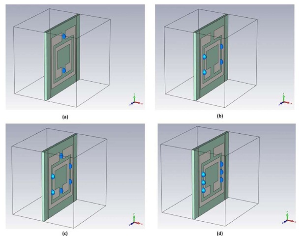
There are four different capacitor layouts examined for the SRR samples, shown in Fig. 2. The first layout (layout A) has the cantilevers with one cantilever set in each of the split ring gaps. Based on the work of Lundell in [12], the intra-ring capacitance is expected to have a greater impact than the gap capacitance with the larger structures. Layout B is created to examine this conclusion, having two sets of intra-ring cantilevers on each side of the cell for this layout. Layout C is a combination between layouts A and B, with sets of cantilevers in each of the split ring gaps as well as two sets of intra-ring cantilevers per side of the unit cell, six sets of cantilevers in total. Layout D is similar to layout B, having three sets of intra-ring cantilevers on each side of the cell. The variable capacitors are modeled as lumped element capacitors, depicted as the blue objects in Fig. 2.
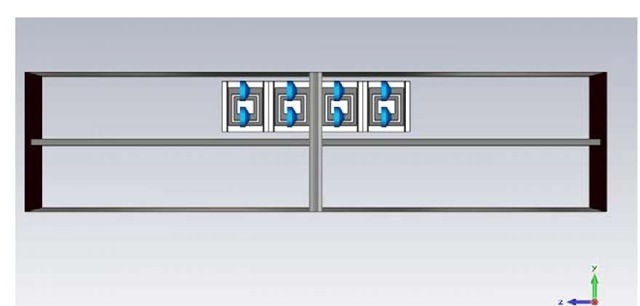
The AFIT adaptive metamaterial structures are designed to be tested using a stripline waveguide designed for operation up to 4 GHz. To match experimental conditions, the devices are modeled in the simulated waveguide structure. The simulated cross sectional dimensions of the waveguide model match the physical dimensions of the waveguide. All metal pieces are modeled as perfect electrical conductor (PEC), and all boundaries are set to open. The length of the stripline is greater than three times the length of the longest sample to be measured in the physical stripline. The number of port modes simulated is set to four for all simulations of the AFIT adaptive metamaterial structures in the simulated waveguide. It is assumed that the physics of the structures is captured within these four modes and that higher order modes will have decayed before reaching the waveguide ports. The simulated device with capacitor Layout A is shown in Fig. 3.
Fig. 2: AFIT metamaterial unit cell variants. (a) Layout A with cantilevers in the gaps of the split rings. (b) Layout B with two set of cantilevers between the inner and outer split ring per side of the cell. (c) Layout C with sets of cantilevers in the split ring gaps and two sets per side of the cell. (d) Layout D with three sets of intra-ring cantilevers per side of the cell.
Fig. 3: Model of the AFIT adaptive metamaterial structure with capacitor layout A in the model of the physical stripline.
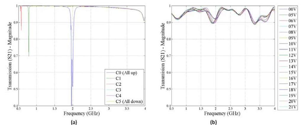
The simulation and measurement of the structure with capacitor layout A are shown in Fig. 4(a) and Fig. 4(b) respectively. The simulation results show an area of resonance above 2 GHz for C0, which shifts to below 0.5 GHz by C3. The stripline measurements were taken at 0 volts applied and then at every volt from 5 to 21 volts. The measured transmission data from the 3 GHz sample with capacitor layout A is shown in Fig. 4(b). A region of shifting resonance is seen around 2 GHz. The resonance is seen to shift from 1.98 GHz at 0 volts applied to 1.89 GHz at 21 volts applied, a difference of only 0.11 GHz or 5.5% of the original resonance frequency. The small shift is due to the small range of voltages applied. In the interest of sample preservation, the range of applied voltages was limited to fewer than 22 volts, as previous samples with capacitor layout A shorted at 25 volts.
Fig 4: (a) Simulation and (b) measurement results from AFIT metamaterial device with layout A.
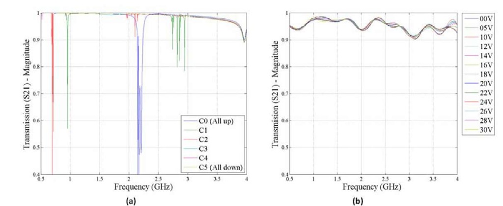
Simulated and measured transmission results for the AFIT metamaterial structure with cantilever layout B are depicted in Fig. 5. The transmission data is clouded by multiple resonance areas. There appears to be a shifting resonance area at 2.25 GHz that shifts downward with increasing capacitance. At C0, the single region is seen around 2.25 GHz. For C1 and C2, two shifting regions are seen. For C3 through C5, the resonance appears to have shifted below 0.5 GHz. The stripline measurements were taken at 0 volts, 5 volts, and every two volts from 10 volts to 30 volts. The measured transmission data is shown in Fig. 5(b). With increased voltage, the transmission nulls are seen to shift slightly, only 0.052 GHz and 0.050 GHz for the 2 and 3 GHz resonance regions respectively.
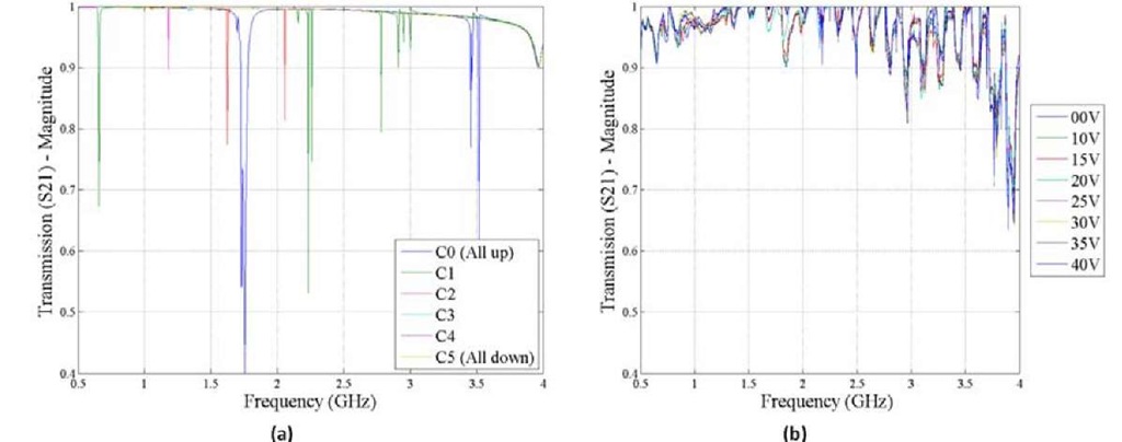
Simulated and measured transmission results for the AFIT metamaterial structure with cantilever layout C are shown in Fig. 6. From the simulation data, the C0 results show two resonance regions at 1.75 GHz and 3.5 GHz which shift to 0.75 GHz and 2.25 GHz for C1, respectively. There is also a third resonance region for C1 at 2.75 GHz. The resonance regions shift out of the frequency range as the capacitance values increase. The increased number of capacitors adds to the complexity of the transmission data. The stripline measurements were taken at 0 volts applied then at every 5 volts from 10 to 40 volts, where the sample shorted out. The measured transmission data from the 3 GHz sample with capacitor layout C is shown in Fig. 6(b). A large oscillation is present in the transmission data above 2 GHz; therefore data above 2 GHz should be disregarded. Transmission nulls are seen around 0.5 GHz and just below 2 GHz. The transmission data does not change with applied voltage at the 0.5 GHz transmission null; however there are changes at the 2 GHz transmission data. Even with the changes at the 2 GHz transmission data, no appreciable null shift is seen, only a slight decrease in the transmission amplitude is observed. In this region, the calibration appears poor, with transmission measurements above unity, a non-physical result. It should be noted that this set of measurement data was obtained without applying time domain gating to the measured data.
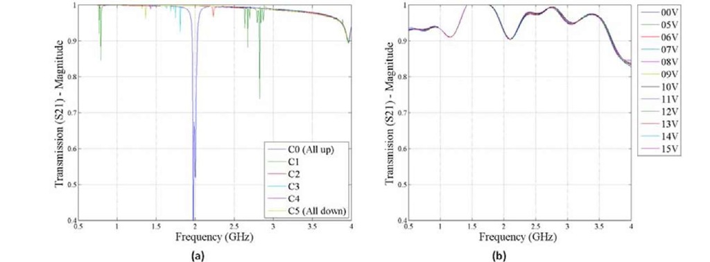
Simulated and measured transmission results for the AFIT metamaterial structure with capacitor layout D are shown in Fig. 7. Similar to capacitor layout C, multiple resonance areas are seen in the simulation results. There is an area of resonance at 2 GHz for C0 that appears to shift below the frequency range for greater capacitance values. There is also a resonance region around 2.75 GHz for C1 that shifts to around 1.25 GHz for C5. The stripline measurements were taken at 0 volts and at every volt from 5 to 15 volts. The measured transmission data from the 3 GHz sample with capacitor layout D is shown in Fig. 7(b). Transmission nulls are seen around 1 and 2 GHz; however here is no shifting seen as the voltage is increased.
Fig 5: (a) Simulation and (b) measurement results from AFIT metamaterial device with layout B.
Fig 6: (a) Simulation and (b) measurement results from AFIT metamaterial device with layout C.
Fig 7: (a) Simulation and (b) measurement results from AFIT metamaterial device with layout D.
Having reviewed simulated results from all four variants of the larger AFIT metamaterial structure, recommendations can be made for design improvements. While there are clear resonance shifts observed for the structures simulated with additional intra-ring capacitance, the multiple resonance areas complicate analysis.
Also, cell to cell variance of additional capacitance in the physical devices can limit the strength of the resonances. The single resonance frequency provided by layout A provides transmission results that are easily evaluated for resonance frequency shifts. The effective capacitance change required to achieve a shift within the frequency range of the stripline is examined. Various capacitance values are simulated and the resonance frequencies are calculated. Based on the simulated resonance frequencies for layout A, a non-linear increase in effective capacitance values is recommended. To achieve a shift from 2.3 GHz to 1.0 GHz, a change of capacitance from 0.1 pF to 1.5 pF needs to occur. The other layouts are not recommended for further design improvements. As the number of capacitors is increased, the strength of resonant mode coupling is decreased because of the variance in actual effective additional gap capacitance provided by the physical cantilever structures, leading to little shift of the resonance frequency observed in the measured results.
Conclusions
Full wave electromagnetic simulations and measurements of larger scale AFIT metamaterials are combined in this research to determine the most promising structure for changing the resonance frequency. For the four capacitor layout variants created, a single cell model is refined to represent the structures as measured, 4-cell long columns in a stripline. The single resonance frequency provided by capacitor layout A provides transmission results that are most easily evaluated for resonance frequency shifts. To achieve a resonance frequency shift from 2.3 GHz to 1.0 GHz, a change of effective additional gap capacitance of 0.1 pF to 1.5 pF needs to occur. To achieve a linear step decrease in the resonance frequency, thicker cantilever beams with geometries that will provide the additional capacitance are recommended. The thicker beams would provide a more discrete change in additional capacitance and therefore a more discrete change in resonance frequency.
The remaining layouts are not recommended for further design improvements. As the number non-uniformly actuating capacitors is increased, the strength of resonant mode coupling as decreased, as seen in measurements of the samples. Stronger resonance regions would be achieved if the MEMS structures actuated uniformly across the cells.

![An adaptive DNG metamaterial design that uses cantilever beam variable capacitor [10]. An adaptive DNG metamaterial design that uses cantilever beam variable capacitor [10].](http://what-when-how.com/wp-content/uploads/2011/07/tmp16213_thumb_thumb.jpg)
