Environment Tab
Reflect for a moment about reflection. (Wow, that was lame!) But if you look at an object and see a reflection, its contents aren’t determined by the object itself but by its surroundings, right?
In a 3D setting, surface reflections often include other models within a scene, and those reflections typically are created via a process called ray tracing, which generates reflections and shadows based on the location of objects and light sources within a scene. Reflections can also include images of objects that don’t exist as models in a scene; reflections of "offstage" objects or backdrops are created as 2D images, which you then overlay onto the reflective surface, a technique known as reflection mapping.
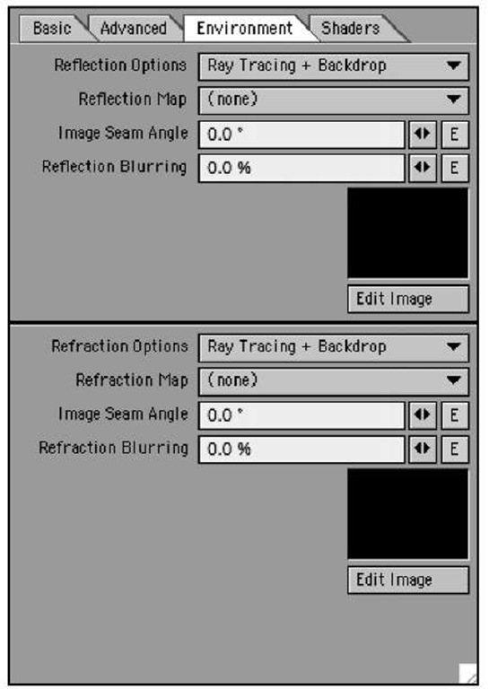
The Reflection attribute in the Basic tab controls how reflective a given surface will be; settings in the Environment tab (Figure 3.14) control what appears in reflections generated by the surface. When you’re dealing with a transparent surface, the tab provides comparable control over how the surface refracts objects placed behind it in a scene.
On the Environment tab, you can assign the following:
• Reflection Options. The type of reflection applied to a surface: spherical, ray trace, or backdrop
• Reflection Map. What image will be reflected
• Image Seam Angle. Where the seam of a reflected image will appear
• Refraction Options. The type of refraction applied to a surface, either spherical or ray trace
• Refraction Map. The image file used (if any) for refraction
• Image Seam Angle. Where the seam of a reflracted image will appear
• Reflection Blurring. The amount of blur your reflections will have
Figure 3.14 The Environment tab gives you access to reflection and refraction controls.
The best way for you to get a feel for using the Surface Editor and the Basic and Environment tabs is to try them out for yourself. An excellent way to observe the effect of the settings you choose is to use LightWave’s VIPER feature.
Working with VIPER
VIPER stands for Versatile Interactive Preview Render, and it gives you a previews of certain types of adjustments you can make to your scene in Layout, such as volumetric settings and surface settings. It’s important to point out that because VIPER does not do a full-scene evaluation, some aspects of your surfacing are not calculated, such as UV mapping and shadows. This means that VIPER is limited in what it can show. However, it is very useful for most of your surfacing needs, such as specifying color and texture. As you adjust your surfaces, VIPER shows you what’s happening and how the surface will look in your scene, without the need to re-render the whole scene. VIPER is available in Layout only.
Note
VIPER’s ability to preview surface attributes and other effects extends only to changes made using LightWave’s built-in editor panels.VIPER cannot display effects or changes made using third-party plug-ins such as FPrime from Worley Labs (www.worley.com).
Exercise 3.1 Using VIPER with Basic Surfacing
To get an idea of how useful VIPER is, try this quick tutorial.
1. Start Layout, or if it’s already running, save any work you’ve completed so far and choose Clear Scene from the File drop-down menu (keyboard equivalent: Shift+n).
Note
You don’t always need to clear the scene before loading a scene. Simply loading a scene overrides your current scene.This two-step process familiarizes you with the available tools and Layout’s workflow.
2. Choose Load Scene from the Load drop-down and open Planet_Anim.lws (located in the Gradients folder, inside the Scenes folder provided to you with the NewTek LightWave v9 content). You’ll see a green blob.
3. Press F5 to open the Surface Editor panel.
You’ll use VIPER to preview changes made in the Surface Editor, which must be open for VIPER to render and display the surfaces you set.
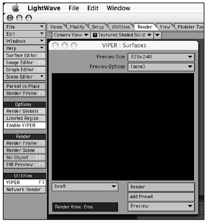
4. Click Layout’s Render tab, and then click the VIPER button in the Utilities tool category. When you do, the VIPER preview window opens and the Enable VIPER button (in the Render tab’s Options tool category) is activated automatically (Figure 3.15). (Press F7 in any Layout tab to accomplish the same thing.)
When you click VIPER in the Render tab or press F7 to open the VIPER window, VIPER is enabled automatically. Repeating either of those operations closes the window, but leaves VIPER active until you toggle it off using the Enable VIPER button—something you may want to do before running full frame or scene renders.
Figure 3.15 The VIPER command is found in Layout only, on the Render tab.
Note
Here’s the lowdown on the two VIPER-related buttons in Layout’s Render tab. The Enable VIPER button makes VIPER pay attention to the rendering buffer, which allows it to preview surface changes in its Display window. The VIPER button opens and closes, the VIPER window. Disabling VIPER with the toggle button allows you to leave the VIPER preview window open but frees up system resources to speed frame and scene renders.
5. With the VIPER window now open, click the Render button at the bottom of the VIPER panel. An error appears stating that VIPER has no surface data to render. Click OK to close the error window.
This is normal. For VIPER to work, it needs you to render a frame so that it can store information from a buffer. Otherwise, VIPER has no idea what’s in your scene.
6. Click OK to close the error window, and then press F9 to render the current frame.
This renders the current frame and stores the information in LightWave’s internal buffer and lets you see surface-setting changes through VIPER.
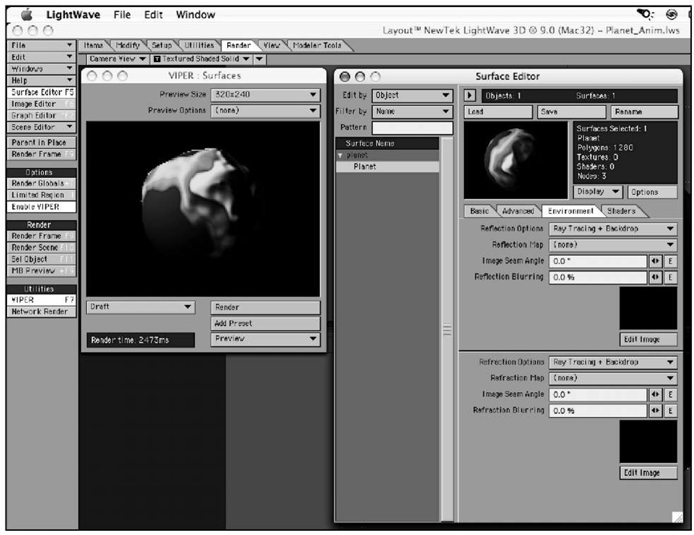
7. After the frame renders, press the Escape key (Esc) to close the Render Status window. If it’s in your way, move the Image preview window to one side. Then, in the VIPER window, click the Render button again. Do you see anything? The render you just created is now appearing in the VIPER window. Figure 3.16 shows the VIPER window once it has loaded and stored render settings such as Specularity, Diffuse, and Color. The previews in the VIPER window and Surface Editor’s preview window differ somewhat because Surface Editor’s preview uses a standard perspective or orthographic view of your object, while VIPER previews the scene from the viewpoint of your selected camera (thereby mimicking your intended results more closely).
Figure 3.16 Pressing F9 on the keyboard renders the current frame and lets you preview surface changes through VIPER.
Note
It doesn’t matter with a simple "scene" like this, but for more complicated scenes, you might want to disable VIPER while rendering the frame, then turn it back on before continuing.
8. In Surface Editor, choose Planet from the Surface Name list. It’s the only surface in the scene, and it belongs to the only loaded object, called planet. (To see the surface name, you may need to click the white triangle to the left of the object’s name.)
9. To quickly see VIPER’s interactivity, click the mini-slider to the right of Diffuse in the Surface Editor’s Basic tab. Hold down the mouse button and slide your mouse to the left to take the value down to 0, and then release the mouse button. You’ll see the VIPER window update, to make the planet appear black. What you did was tell the surface not to receive any light from the scene, essentially turning off the lights for that surface.
10. Now, restore the Diffuse value to 100% and continue.
You’ll see various surface settings appear throughout the commands on the right, on the Basic tab.
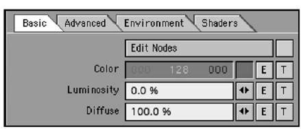
11. Click the T button to the right of the Color control to open the Texture panel for the planet object (Figure 3.17).
Figure 3.17 Clicking any of the T buttons throughout LightWave, including the Surface Editor, opens the Texture Editor.
Note
If the T button to the right of the Color control is dimmed, uncheck the Edit Nodes box located immediately above it.
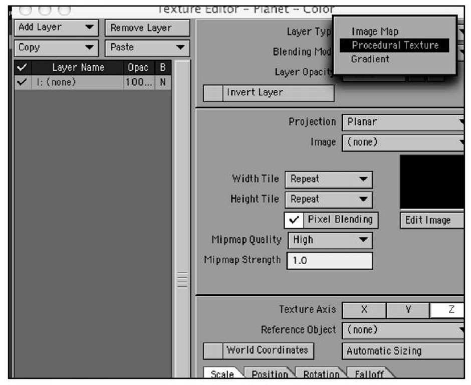
You’ll see that the Layer Type at the top of the commands is set to Image Map—a setting that lets you apply images to a surfaces and much more, as we’ll see later in the topic. For now, change the Layer Type to Procedural Texture, as in Figure 3.18.
Figure 3.18 The default Texture Editor Layer Type is Image Map. Change this to Procedural Texture instead.
Procedural textures have no seams, and are often just what the doctor ordered for organic-looking surfaces. They vary surface attributes via mathematical procedures; each procedural type yields a different effect. By changing procedure settings within the Texture Editor and combining procedural textures in various ways, you can create a limitless range of organic surfaces.
The Procedural Type is set to Turbulence, a variation of fractal noise that has been used by LightWave animators for years. Adding Turbulence as the Procedural Type to the current surface color of the planet, which is a bright green, adds variances to the surface.
The Blending Mode is set to Normal, which tells LightWave to add this procedural texture to the selected surface. (Other Blending Mode settings are used when you apply multiple textures to a surface; they determine how textures combine with each other.)
The Layer Opacity is set to 100%, telling LightWave to use this procedural texture to the fullest extent.
12. Make sure the VIPER window is open and visible to the side of the Texture Editor.
If VIPER is not open, click the VIPER button (not Enable VIPER) in Layout’s Render tab. You rendered the scene in step 5, and LightWave remembers that by storing the data in its internal buffers.
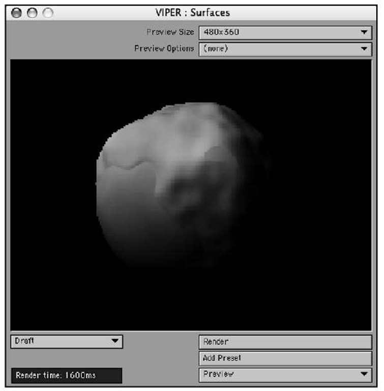
13. With the Texture Editor and VIPER open, you can make changes to surface settings and see your changes in real time. Figure 3.19 shows the VIPER panel.
Figure 3.19 Once you’ve made a render of a frame (by pressing F9),VIPER can now display the render, and you can make surface changes in the Texture Editor (among other places) and see them in real time.
Note
The VIPER preview window has default size of 320×240 pixels. In Figure 3.19, we’ve expanded it to 480 x 360 pixels using the Preview Size drop-down. Adjust the preview window to suit your screen size.When you do so, there’s no need to re-render your image. However, if you change scene lighting or object position, or add or remove objects in the scene, you need to re-render by pressing F9.
14. Make certain that the Texture Editor is still open (you got to the Texture Editor by clicking the T button next to Color in the Surface Editor).
You can see from the VIPER preview window that the beautiful green surface is now sort of dusty-looking. This is because the basic default procedural texture was applied when you chose Procedural as the Layer Type.
15. Because the procedural turbulent noise texture was a little too heavy, change some of the parameters, such as Size, found at the bottom of the Texture Editor panel on the Scale tab. Click and drag the X, Y, and Z values and watch VIPER redraw your image with the surface changes.
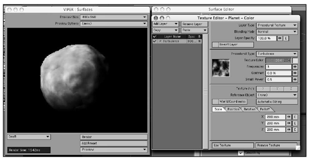
16. Experiment with the other procedural type settings such as Underwater or Crumple. From there, try to use other procedurals and adjust their properties as well. Figure 3.20 shows the Texture Editor and VIPER with a default Procedural Texture of Turbulence applied and the Scale made smaller.
Figure 3.20 Changes to texture-property values such as Color, Scale, and Contrast are easy to see with the VIPER window open.
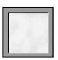
To the left of the Texture Color setting in the Texture Editor window is a small square display. This area shows your procedural pattern. The base background color for the procedural is black. When combined with a dark texture color, this makes a hard-to-see swatch. To remedy this, right-click on the swatch and set a new background color. In addition, you can left-click on the Display window and drag the preview around. Doing this helps you see more of the procedural pattern. Figure 3.21 shows a close-up. Mac users with single-button mice, remember to Cmd-click for right-mouse button commands.
Figure 3.21 You can change the base background color for your procedural texture display by right-clicking in the Display window.
VIPER will quickly become one of your best friends when you’re working with LightWave Layout because it saves you time. Not only that, many of you may not be mathematical wizards and do not care to calculate every value within the surface settings. Using VIPER can answer many of your questions when it comes to surfacing because you can instantly see the results from changed values. It’s guaranteed that during your practicing, you’ll utter a loud "Oh, that’s what that does!" from time to time.
