Imagine that LightWave is a virtual television studio and 3D models are your actors. Although some animations can be created with animated textures or photographs, most include 3D models. These models are made up of points, edges, and polygons. This topic takes you on a tour of LightWave Modeler. Along the way, I’ll explain points, edges, and polygons and show you how to use them to create 3D objects—which you will then animate and render in LightWave Layout.
LightWave Modeler is where your 3D animations begin. That’s not to say you can’t start animating right away. NewTek Inc., the makers of LightWave, have included a terrific amount of prebuilt content for you to use and explore. In fact, you can load a sample scene in LightWave v9 Layout and click the Render button to create your very first animation without ever launching Modeler. But to really know your software, you must first understand what a 3D model is all about.
Note
If you only plan to animate, and never plan to model, you might wonder if you should even read this topic.The answer is yes! Even if you never plan to model in your career, it’s still important to understand LightWave Modeler for a couple of reasons. You may at some point need to import a model from another program. Or, at the very least, you’ll need to assign a surface to parts of your model. You can only do that in Modeler.
LightWave Modeler has evolved into one of the most advanced tools of its kind, and enhancements in version 9 take it to a new level of power and sophistication.
Consistent with its complex abilities, Modeler has many buttons, panels, and menus, but there’s no need to be intimidated if you stay focused on the task you want to accomplish. All the tools are useful, but many tasks require only a few of them at once. You’ve probably heard this before: You’ll use only 20 percent of the tools 80 percent of the time. As with any fully equipped software program, some general-purpose tools get used every day; more specialized ones get pulled out once in a while—so you should always know what’s in your toolbox.
Note
Please, by all means, before you go any further, read the info in the front of the topic about the Content Directory and how to set it up. In fact, stop now,and do it. We’ll wait.
This topic will explain all of LightWave’s tools, and help you find the ones you need to get your work done. This topic begins by covering the features of Modeler. And speaking of Modeler, did you read about the Content Directory in the front of the topic? Make sure you do!
There are practically no limits to what you can create using 3D animation, which means a virtually unlimited number of variables to manage—and a vast number of tools within LightWave to control them all. However, I want you to ignore the overall cluster of buttons in LightWave and concentrate instead on the tools and what you are trying to do. In other words, don’t get overwhelmed by the buttons. I can’t stress this enough. There are times when you will use only half a dozen buttons and tools for an entire project. Often, your particular type of work may never even unwrap some of the tools and panels LightWave has to offer. And there’s nothing wrong with that. The goal of this topic, and more specifically this topic, is to help you understand how to use LightWave Modeler and work with its toolset. Even with so many improvements in LightWave over the years, version 9 includes some of the most complex changes to date. LightWave Modeler has been touted as one of the best 3D modelers in the industry, and the latest update makes it a more efficient, powerful tool, with much enhanced workflow. This topic introduces you to that workflow. Here are some of the key areas discussed in this topic:
• LightWave v9 Modeler interface navigation
• Viewports
• Simple objects
• Points, edges, and polygons
• Selection and deselection
• Splines and subdivisional surfaces
Proper construction of 3D models and animations takes discipline, focus, and a keen sense of direction. And, just as if you were building a cabinet in your garage or redoing the tile in your own bathroom, it also requires careful planning and a full understanding of the tools involved. This is because you want your 3D models to be efficient. That is, you have to construct the models properly so that you can animate them correctly. When you know your tools and methods, the goal is not difficult to accomplish. Your focus should be clear and your work environment should be comfortable. There’s nothing worse than working on a complex model without a plan and in an uncomfortable workspace. Be prepared, both mentally and physically.
3D Modeling in LightWave
Before we start using Modeler, you should become familiar with the medium that is 3D animation. You should understand how the X-, Y-, and Z-axes relate to one another and your LightWave workspace.
Note
Too often when people work in 3D, either in modeling or animation, they only consider the flat screen in front of them. Do not make this mistake! Remember that your 3D models are more than just what’s visible in front of you—they have sides, a top, a bottom, and a back, even if you can’t see them.
3D modeling is like interactive geometry. You can begin creating models with simple points and connect them with curves or straight lines. LightWave also gives you a slew of basic geometric shapes such as boxes and spheres to work with, and you’ll see throughout this topic just how those basic shapes can be used to create complex 3D models. Before you concern yourself with building complex 3D models, however, let’s take a look at how the LightWave interface is laid out.
LightWave v9 Modeler Interface
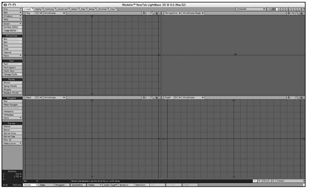
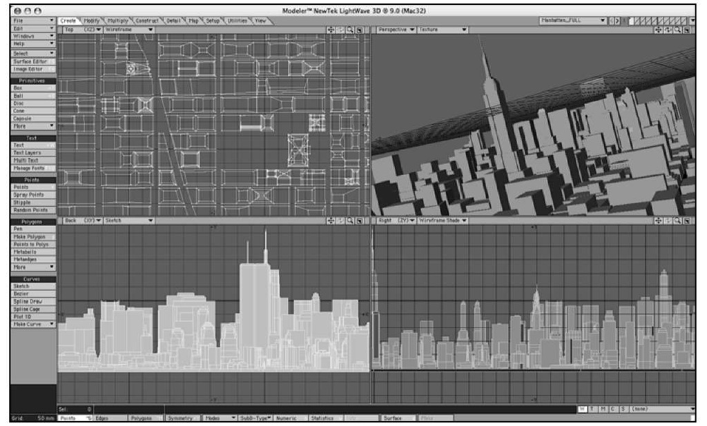
If you’re new to LightWave with version 9, the interface (Figure 1.1) will obviously look unfamiliar. Initially, working through the interface might be frustrating, but if you understand the tools and their arrangement and keep in mind what you want to do, you’ll find using the program simpler than you might think.
If you’re an experienced LightWave user and have just upgraded to LightWave v9, you’ll notice at first a similarity to previous versions. With version 9, LightWave adds some great new tools and rearranges some preexisting ones to bring them closer to the surface. Both LightWave Layout and Modeler have been significantly streamlined and navigation has never been easier, but the changes may require some adjustment.
Although much of this topic focuses on the modeling tools in action, this section highlights the features of LightWave v9 Modeler. You’ll be able to try them out in just a few steps to gain a strong working knowledge of their functions.
Figure 1.1 The LightWave 3D Modeler interface.
Modeler Viewports
To begin working with LightWave v9 Modeler, you should understand the viewports first. These four windows are the areas that will be your work environment, and by default, they show all sides of your 3D model.
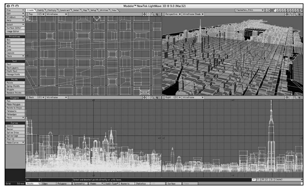
Take a look at Figure 1.2, which shows the same full Modeler interface as Figure 1.1, but this time with a 3D model loaded. By default, LightWave Modeler assigns the viewports Top, Back, and Right views of your model, along with a Perspective view. Each is a little awkward at first, but try to remember this:
• Top view (XZ) provides a view along the Y-axis. You are looking down at the top of your object.
• Back view (XY) looks down the Z-axis. You are looking from the back of your object toward its front.
• Right view (ZY) looks down the X-axis. You are looking at the left side of your object, toward its right.
Yes, this may sound confusing, but after you get used to the concept, it will make more sense. And eventually, it’ll even become familiar. For instance, when you get to Layout later, you’ll find that the Back view you see in Modeler is the default view that the LightWave camera sees. The LightWave camera looks toward the back of the object, forward in the scene.
Figure 1.2 A 3D model of Manhattan loaded into LightWave Modeler can be seen from all sides, and the default layout also shows a solid color version.
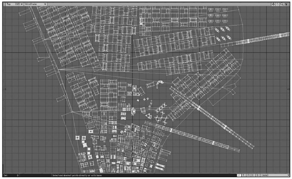
Don’t let this layout of viewports make you feel constrained. You can change any viewport to look any way you like. Check out Figure 1.3, where a close-up of the top-left viewport is shown.
Figure 1.3 A close-up of the upper left viewport, with some geometry loaded.
This top-left viewport is called Top by default, and it shows the 3D object from above—you’re looking at the "top" of the object. Notice that at the top of the viewport there are buttons labeled Top (XZ) and Wireframe. This tells you that the particular viewport is set to Top. The XZ means these are the two axes you have control over. Because you’re looking down the Y-axis, you can’t move your object along that axis in this view.
Figure 1.4
The four small icons at the top right of each viewport enable you to move, rotate, zoom, and maximize the viewport.
At the top right of the viewport, you’ll see four small icons. These are your viewport position controls. Figure 1.4 shows the buttons up close.
Note
Depending on viewport settings, certain position control icons may be dimmed to indicate they are unavailable. In the Top viewport, for instance, the Rotate icon is dimmed because you can only rotate in a Perspective view, not an orthogonal (X,Y,Z) view.
Click, hold, and drag on these buttons to use them. Too often, people click them and release, but that’s not how they work. Click and hold to use! The first button is Move, the next is Rotate, the third is Zoom, and the last is the Maximize viewport button. Click this one, and your viewport will become full screen. This is great for getting up close to your model for fine-tuning point position or measurements. To return from a full-screen viewport, just click that icon again.
Note
If your keyboard has a numeric keypad (most nonlaptop models do, and some laptops sport them, too) you can use its 0 key in place of the Maximize viewport button. (That’s 0, as in zero, and in the numeric keypad only; you’ll use the number keys at the top of your keyboard to change layers.) Be sure your mouse cursor is in the viewport you want to maximize before pressing the 0 key. Press 0 again to return from full-screen mode.
Viewport Customization
You can customize each of the four viewports in Modeler any way you like. In Figure 1.5, you can see that you can assign any or all viewports a Back, Top, Right, or Perspective view. You can make all four viewports Top views if you like, although it might not help your modeling process too much.
Figure 1.5 Each viewport can be set to any view you like. Here, with a simple wagon object loaded, the Top left is a Front view now, the Back is set to Bottom, while the Right view is now a Perspective view.
Note
Although LightWave v9 is extremely customizable, the projects in the topic will use the default configurations for Modeler and Layout, for the sake of consistency.
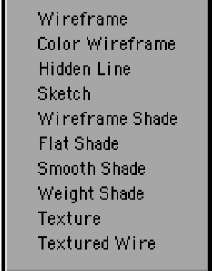
Something you might change more often than the viewport view is the viewport style—its method of drawing the objects it depicts. Choosing any of the 10 settings from the drop-down menu shown in Figure 1.6 lets you visualize models using styles, including Wireframe, Smooth Shade, and Textured Wire. Different styles are better suited to various modeling tasks, as we’ll see later in the topic.
Figure 1.7 shows each viewport set to a different style with a different model loaded, so you can see how flexible the options are.
Figure 1.6
Each viewport can also have a unique viewport style, such as Wireframe or Textured Wire.
Note
Your choice of viewport style will be based on the model you are creating. Often, a good way to work is with the default settings—Wireframe style in the X,Y, and Z viewports,while a Smooth Shade or Textured Wire style is used in a Perspective view. It’s totally up to you.
Figure 1.7 Here, each viewport is set to a different style.There are a total of 10 viewport style choices.
