Create a Cluster of Grapes
This next project will show you how to create a cluster of grapes in LightWave v9 Modeler. Later, you’ll call up this object and place it in a large bowl that you’ll model, along with the banana and orange.
Exercise 8.3 Bunches of Fun with the Clone and Magic Bevel Tools
1. Save anything you’ve been working on, and from the File drop-down menu, select New Object.
You might have noticed that you’re not building with layers in these projects. You could if you wanted to—create the banana in one layer, the orange in another, and the grapes in a third layer. But instead, you’re building entirely new objects. This is good because these objects can be used to build your 3D library, as they are saved as individual objects. It also helps save any confusion as to what you’re working on, and for this project, you’ll use multiple layers to help the modeling process. Having multiple objects in different layers might make your life difficult with the upcoming steps.
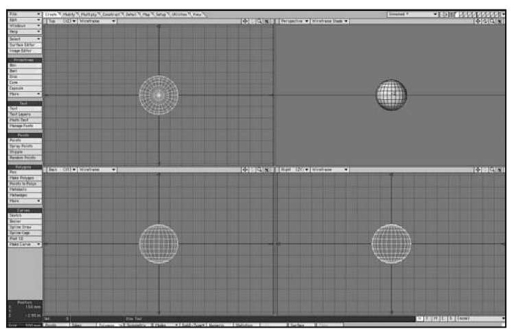
2. On the Create tab, select the Ball tool. Create a ball the same size as you did in the previous project (when you created the orange). Press F2 to center the ball. Figure 8.39 shows the ball.
Figure 8.39 Begin creating grapes by making a simple ball.
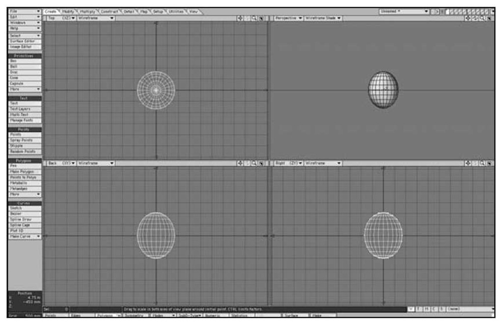
3. Press h to activate the Stretch tool, then click in the Back view and drag up slightly to elongate the ball. Figure 8.40 shows the result.
Figure 8.40 Use the Stretch tool to elongate the ball.
4. Click a new layer at the top right of the interface. Place the ball as a background layer by clicking beneath the slash mark in the first layer.
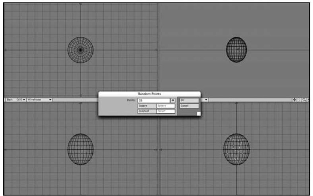
5. On the Create tab, click the Random Points tool in the Points category. In the panel that appears, enter 35 for points, then check on Sphere and Falloff, as shown in Figure 8.41.
Figure 8.41 Use the Random Points tool to create a clump of points.
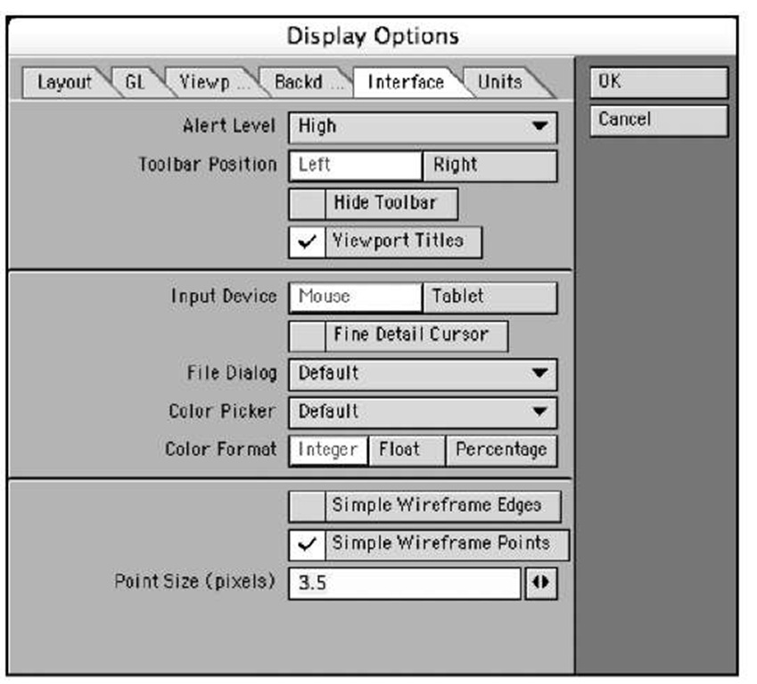
6. You’ll see a group of points created in the views. The points might be hard to see, and there’s a way you can adjust that in Modeler. Press d to call up the Display Options panel. Click the Interface tab, and check Simple Wireframe Points. Set the Point Size to 3.5, as shown in Figure 8.42.
Figure 8.42 Increase the visual appearance of points in the Display Options panel.
7. Click OK to close the Display Options panel. With these points now created, press ‘ (the apostrophe key) to reverse layers. This puts Layer 1 in the foreground and Layer 2 in the background.
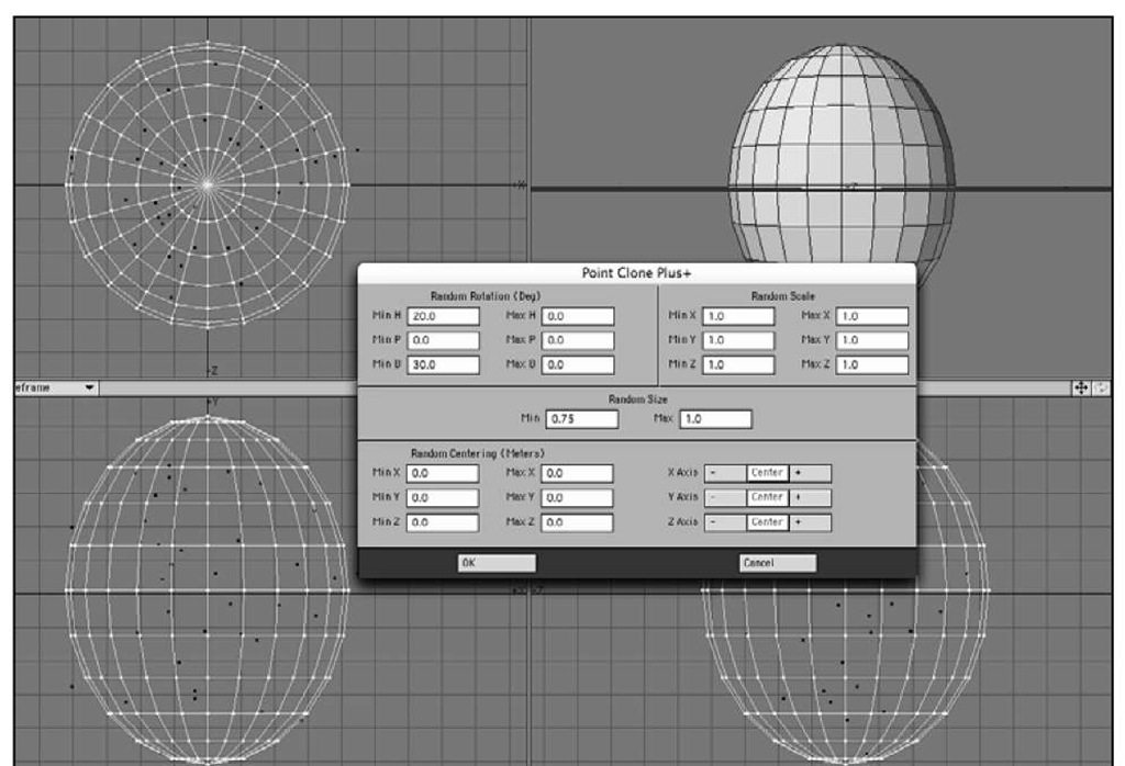
8. On the Multiply tab, click the More drop-down menu in the Duplicate category. Select Point Clone Plus. A large panel appears (Figure 8.43).
9. Enter a few settings: For Random Rotation: Min H 20
Min B 30 For Random Size: Min 0.75 Max 1.0
10. Leave all other settings at their defaults. Basically, the Point Clone Plus tool will generate duplicates of the foreground layer (the ball) based on the position of the points in the background layer. The values you’ve just set are simply adding some randomness to the duplicated objects. Click OK to close the Point Clone Plus tool and see what happens (Figure 8.44).
Figure 8.43 Once the Point Clone Plus tool is set up, you’ll be able to duplicate your foreground object based on the point positions in the background layer.
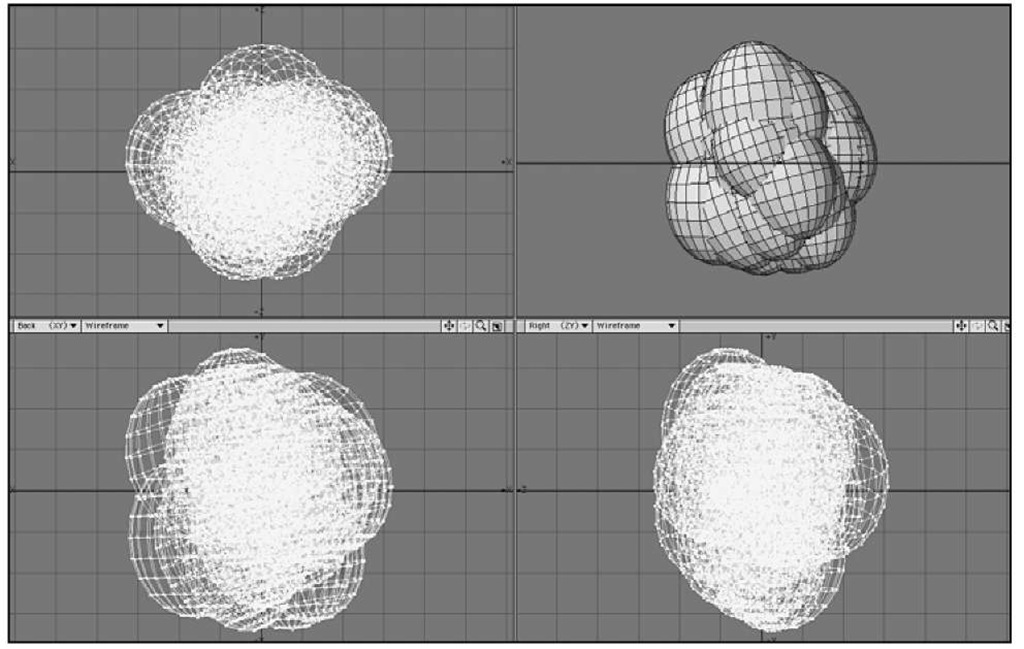
Figure 8.44 The Point Clone Plus tool creates 35 duplicates of the ball (grape), each with randomness throughout.
11. Wow! Those are some fat grapes! Why did this happen? The size of the initial ball was too large based on the position of the points. Click Ctrl+z (Cmd-z on the Mac) to undo the Point Clone Plus operation.
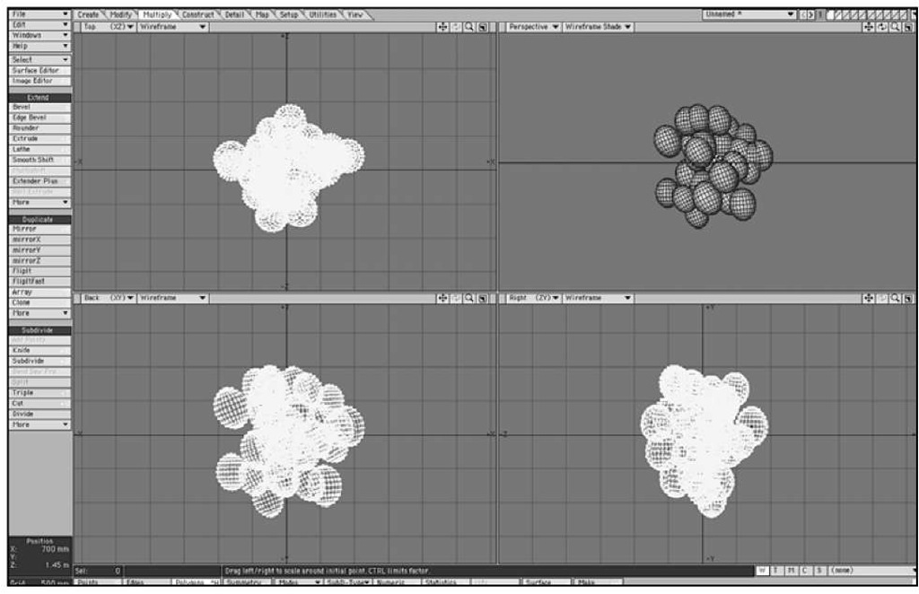
12. Press Shift+h for the Size tool, and size down your grape about 30%. Then, rerun the Point Clone Plus tool. The settings you’ve entered will still be there. Click OK, and you’ll see a clump of grapes, as in Figure 8.45.
Figure 8.45 Using Point Clone Plus along with a ball has created a clump of grapes.
13. A few grapes might be overlapping other grapes, and some might be floating too far out from the rest. You can easily move these with a few steps. Making sure you’re in Polygons selection mode, click once on a grape. Then, press the right bracket key, the shortcut for the Select Connected command. Every polygon connected to that selection (the rest of the individual grape) is now selected. Press t and move the grape.
14. Feel free to resize, rotate, and adjust the grapes as needed. You don’t need to be too precise because these grapes will end up in a bowl, but if you plan to use them later for something more close-up, try to align them more accurately so that none are overlapping. If you feel you need an additional grape or two, select one, press Ctrl+c to copy, move the selected grape, and then press Ctrl+v to paste.
15. To deselect, press the / (slash) key.
16. Continue adjusting the grape positions as you like, and remember to save your work.
17. Press q to open the Change Surface dialog box. Create a surface name Grapes, and give it a bit of color. Perhaps you prefer red grapes over green seedless? Click OK to close the panel and save your object.
18. To create a stem for added impact, go to a new layer, leaving the grapes in a background layer. This process can get tedious to make a branch extend from each grape. However, it’s easy to create the initial look, starting with a box.
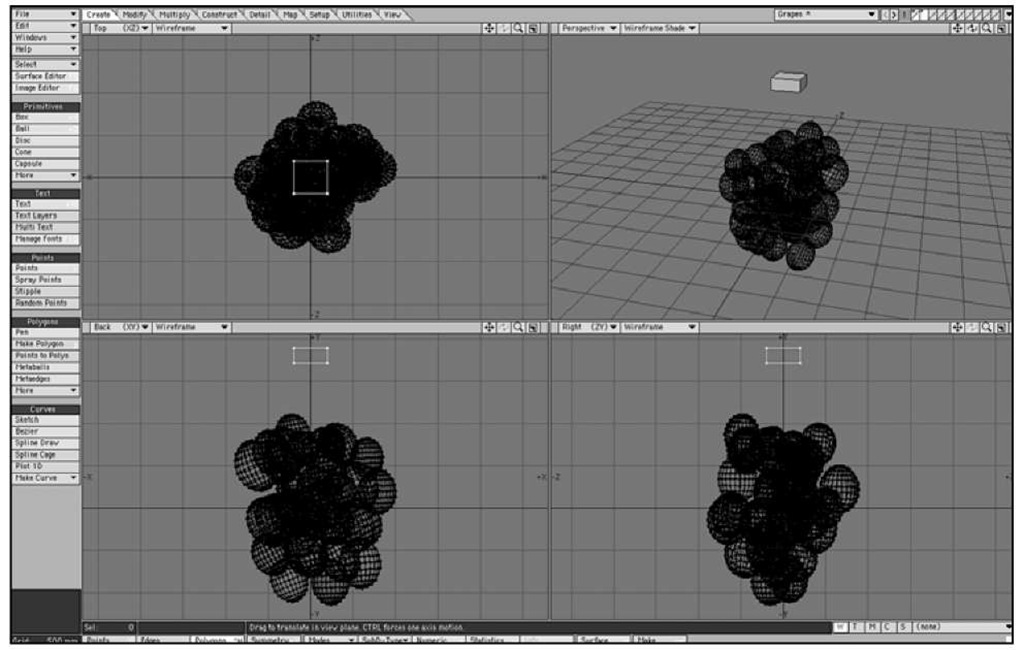
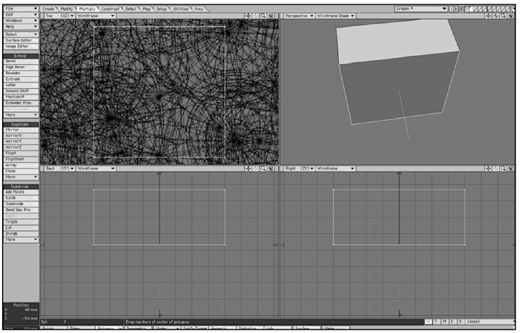
19. Create a small box just above the clump of grapes in the new layer, as shown in Figure 8.46.
Figure 8.46 To begin creating the stem for the grapes, build a small box above the grapes in a new layer.
20. Select just the bottom polygon of the box, as shown in Figure 8.47.
Figure 8.47 Select just the bottom single polygon of the box.
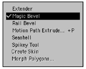
21. Click the Multiply tab, then click the More drop-down menu in the Extend category and select Magic Bevel, as shown in Figure 8.48.
Figure 8.48 Choose the Magic Bevel tool from the Multiply tab’s Extend category.
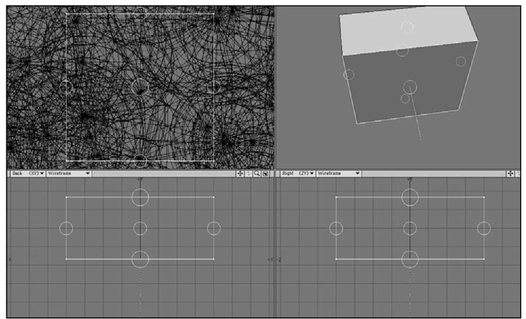
22. When you turn on the Magic Bevel tool, you’ll see small circles appear around the box (Figure 8.49).
Figure 8.49 Magic Bevel begins with small circles on each polygon.
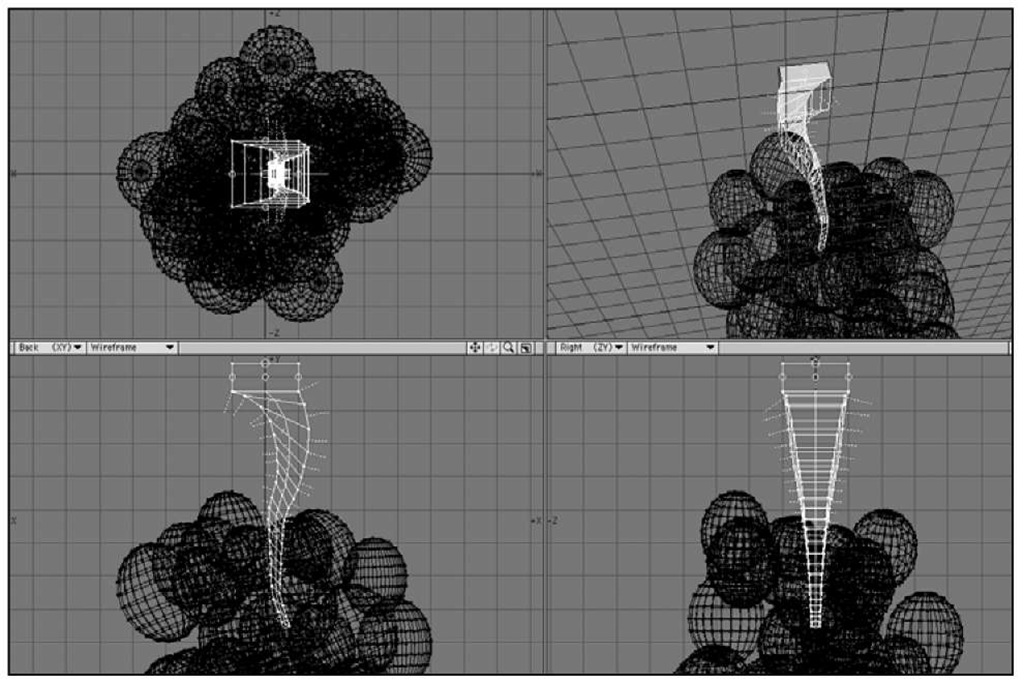
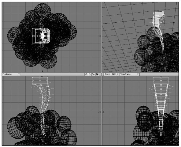
23. Click and drag the circle at the bottom of the box, and drag downward into the grapes. You can do this in the Back or Right view. Feel free to move the mouse slightly to create a curvature. Figure 8.50 shows the result.
Figure 8.50 Click and drag the bottom circle to instantly create a multiple-beveled object.
24. Press the spacebar to turn off the Magic Bevel tool. Then, click its button to turn it on again. You’ll now see circles for the Magic Bevel on each of the newly created polygons (Figure 8.51).
Figure 8.51 Turning Magic Bevel off and then on again resets the tool so you can apply it to newly created geometry.
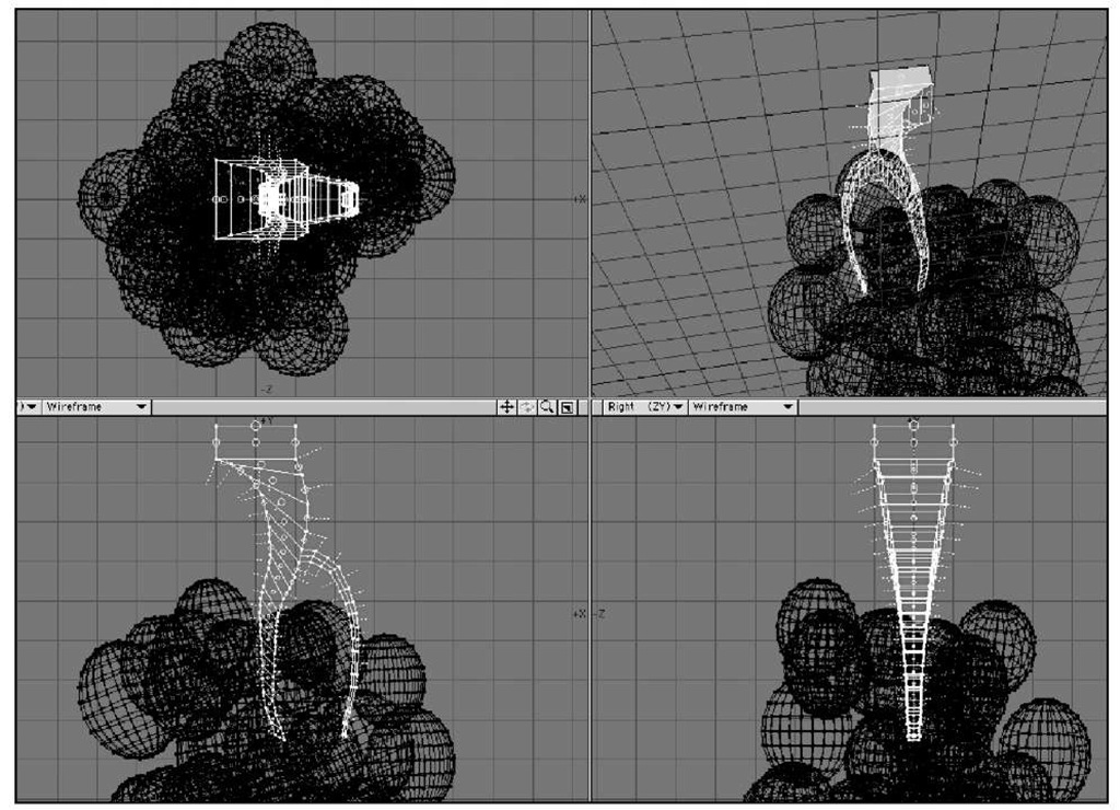
25. In the Back view, click and drag downward from the middle of the stem, creating another branch, like the one shown in Figure 8.52.
Figure 8.52 Create another branch from the middle of the original stem.
26. In the Right view, create another stem.
27. From here, you can apply new Magic Bevels to the stems you’ve created. If you open the Numeric panel, you can adjust their scale. Changing the value to 100% prevents the bevel from tapering as it extends when you click and drag. You can also choose to spin the bevels as they are created.
28. After you’ve created a few branches, press the spacebar to turn off the Magic Bevel tool. Then, press / to deselect.
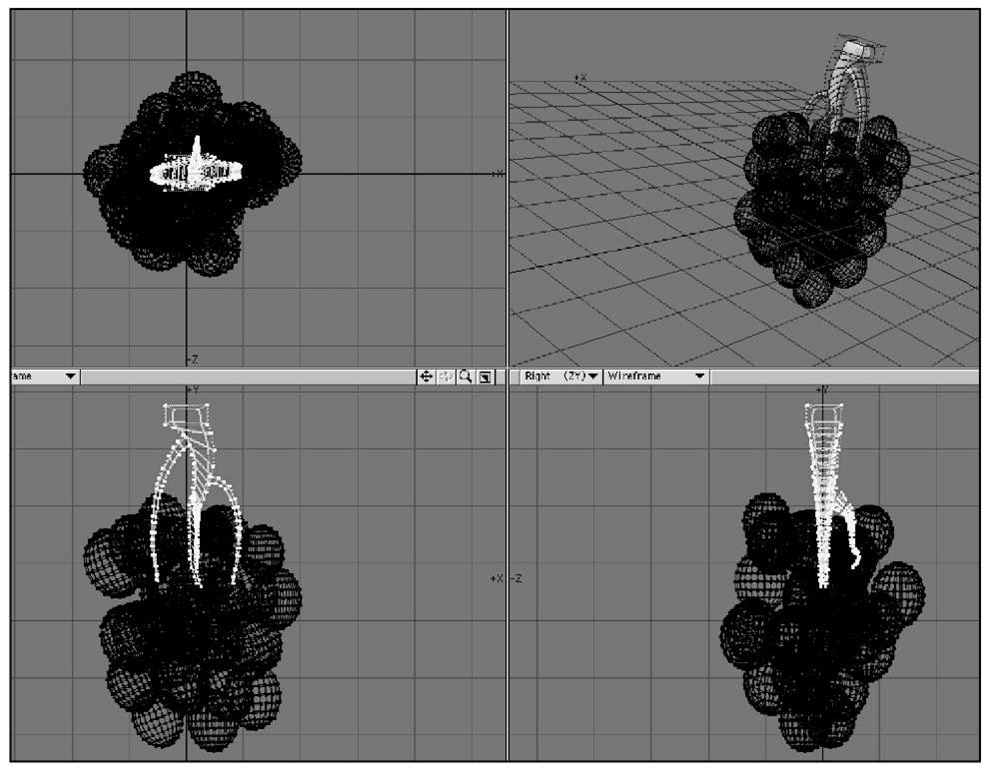
29. Make sure Subpatch is selected in the SubD-Type drop-down list at the bottom of the Modeler interface, and then press the Tab key. You’ll see the beveled box become smooth (Figure 8.53).
Figure 8.53 Apply subdivision surfaces to the stem by pressing the Tab key.
Note
You can also apply subdivision surfaces to the grapes to smooth them out.
30. You can adjust points as you like, and even bevel a single polygon on the stem before you apply a Magic Bevel, to help determine the shape. When you’ve finished shaping the stem, assign it a surface using the Change Surface dialog box (press q).
31. Press Ctrl+x (Cmd-x on the Mac) to cut the stem from the current layer. Switch to the grape layer, then press Ctrl+v (Cmd-v on the Mac) to paste it. Save your object.
The stem is not attached to the grapes, but you can connect it up if you like. Use the Magic Bevel tool to drag a stem bevel right to each grape, or move the grapes around to touch the stem, but keep in mind that the stem is not going to be seen too closely in the final shot, since the grapes will be sitting in a bowl. And hey, speaking of bowls, let’s make one!
