As the name suggests, transition mechanisms help in the transition from one protocol to another. In the perspective of IPv6, transition basically means moving from IPv4 to IPv6. One day, IPv6 networks will completely replace today’s IPv4 networks. For the near term, a number of transition mechanisms are required to enable both protocols to operate simultaneously. Some of the most widely used transition mechanisms are discussed in the following sections.
Dual-Stack
Dual-stack is the foundational and preferred IPv4-to-IPv6 transition mechanism. Dual-stack provides the most natural way for IPv6 hosts and networks to be deployed because no tunneling or translation needs to be performed for end-to-end connectivity. In a dual-stack deployment, both IPv4 and IPv6 are operational on all components (hosts, servers, routers, switches, firewalls, and so on) attached to the network.
The dual-stack mechanism has been used in the past. Previous examples of this mechanism include IPv4 with IPX and/or AppleTalk coexisting on the same node. As with other uses of dual-stack, the IPv4 and IPv6 protocols are not compatible with each other.
The dual-stack model enables the smoothest transitioning from IPv4 to IPv6 environments with minimal service disruptions. This model works by enabling IPv6 in the existing IPv4 environments along with the associated features required to make IPv6 routable, highly available, and secure.
The primary advantage of the dual-stack mechanism is that it does not require tunneling within the network. The dual-stack runs the two protocols as "ships-in-the-night," meaning that IPv4 and IPv6 run alongside one another and have no dependency on each other to function, except that they share network resources. Both IPv4 and IPv6 have independent routing, high availability (HA), quality of service (QoS), security, and multicast policies. Dual-stack also offers forwarding performance advantages because packets are natively forwarded without requiring additional encapsulation and lookup overhead.
The nodes in dual-stack support both protocol stacks (IPv4 and IPv6), enabling them to be configured with both IPv4 and IPv6 addresses. The dual-stack nodes use IPv4 and IPv6 mechanisms such as Dynamic Host Configuration Protocol (DHCP) to acquire their respective configurations like addresses.
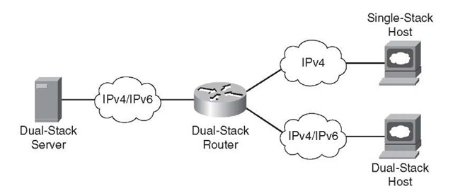
Figure 3-2 shows the dual-stack model. The nodes and the networking devices in this model understand and run both IPv4 and IPv6 independently.
Figure 3-2 Dual-Stack IPv6 Topology
IPv6-over-IPv4 Tunnels
IPv4 is the dominant IP protocol deployed in enterprise networks. As the adoption and deployment of IPv6 grow, IPv6 hosts or entire sections of the network might need to communicate over IPv6 end to end, but IPv4-only portions of the network are in the way. This is common in WAN/branch deployments, where the branch and head-end sites are IPv6-enabled, but the WAN in between supports only IPv4. IPv6-over-IPv4 tunnels encapsulate IPv6 datagrams inside of IPv4, enabling end-to-end communication.
Traditionally point-to-point or point-to-multipoint tunnels have been used to "carry" or transport one protocol, in this case IPv6, over another protocol (IPv4). Tunnels have been used for many years to support Novell IPX/SPX, AppleTalk, SNA, and others.
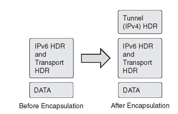
Figure 3-3 shows the basic framework for encapsulating IPv6 inside the IPv4 tunnel header.
There are a variety of tunnel types, and the different tunnel types are used for different purposes. Some of the uses of the tunnel types are based on the termination points (host or router), number of termination points, and in some cases, the operating system version. The tunnel types include
■ Router-to-router: In router-to-router tunneling, routers connected over IPv4 network infrastructure can transport IPv6 packets by encapsulating these IPv6 packets inside the IPv4 header.
■ Host-to-router: In host-to-router tunneling, the IPv4/IPv6 hosts can tunnel the IPv6 packets to an IPv4/IPv6 border router. This tunnel terminates at the border router and from there on is sent natively over IPv6 to the end host.
■ Host-to-host: In host-to-host tunneling, the tunnel exists between the two or more hosts. The IPv6/IPv4 hosts use the tunnel to communicate between themselves by tunneling IPv6 packets within the IPv4 header.
Figure 3-3 IPv6-over-IPv4 Tunnel Encapsulation
IPv6-over-IPv4 tunneling can be further classified into configured and automatic tunneling mechanisms, based on how the tunnel endpoint address is resolved by the encapsulating node. In manually configured tunneling, the configuration information determines the tunnel endpoint addresses, whereas in automatic tunneling, the tunnel endpoint information is dynamically obtained. Some of these methods include
■ Manually Configured Tunnel (MCT)
■ IPv6-over-IPv4 generic routing encapsulation (GRE) tunnel
■ Tunnel broker
■ 6to4 tunnel
■ Intra-Site Automatic Tunnel Addressing Protocol (ISATAP) tunnels
■ IPv6 over MPLS (6PE)
This topic provides a high-level overview of these methods. Refer to subsequent topics for configurations.
Note Some tunneling technologies such as 6rd, Dual-Stack Lite (DS-Lite), and Teredo are not discussed in this topic; 6rd and DS-Lite are geared toward service provider (SP) networks. Teredo is a Microsoft-specific, host-based approach and is generally not used in the enterprise.
Table 3-1 outlines and describes the limitations of these methods.
The next sections describe each IPv6-over-IPv4 tunneling method in greater detail.
Manually Configured Tunnel
Manually Configured Tunnels (MCT) are statically defined IPv6-in-IPv4 tunnels. MCT for IPv6 is supported by most of the stacks and routers; RFC 4213 specifies the methodology for manually configured IPv6-over-IPv4 tunnels for transporting IPv6 packets over an existing IPv4 network. This is one of the first transition mechanisms developed to transport IPv6 over an existing IPv4 network.
MCTs use protocol 41 to encapsulate the traffic, and the tunnel encapsulation is determined from the static configuration information present on the tunneling node. The tunneling node could be a dual-stack router or host. For MCTs, additional information such as the packets of interests are found out based on the configuration/routing table in the node.
Figure 3-4 shows the Manually Configured Tunnel. The end hosts in this model run IPv6, while the routers between which the tunnels exist are dual-stack. The network over which the tunnel is formed is an IPv4 network.
Figure 3-4 Manually Configured Tunnel
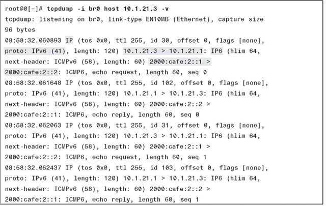
Example 3-1 shows the packet capture with MCTs. The tcpdump shows the IPv4 HDR in front of the IPv6 header. The outer header (IPv4) shows that the IPv4 tunnel is between 10.1.21.3 and 10.1.21.1 (highlighted), while the inner IPv6 header has addresses 2000:cafe:2::1 and 2000:cafe:2::2 (highlighted).
Table 3-1 IPv6-over-IPv4 Tunneling Methods
|
Method |
Description |
Limitations (if any) |
|
Manually configured tunnels |
Supported by all implementations. Standards-based (RFC 4213). |
Difficult to manage as the number of sites increases the operation effort increases exponentially as due to increase in number of sites the number of tunnels increases if fully mesh connections are desired (scalability). |
|
IPv6-over-IPv4 GRE tunnel |
Uses IPv4 GRE tunnels. From a tunnel configuration perspective, this is same as Manually Configured Tunnels. |
Same as Manually Configured Tunnels. |
|
Tunnel broker |
Standards-based (RFC 3053). Requires dedicated tunnel brokers. Dynamic tunnels. |
Tunnel broker service needs to accept configuration changes remotely, which leads to security implications. |
|
6to4 tunnel |
Standards-based (RFC 3056). Automatic tunneling. Uses IPv4 infrastructure such as a virtual broadcast link. Uses 2002::/16 as a prefix. |
Underlying IPv4 address determines the 6to4 IPv6 address prefix, so migration to native IPv6 requires renumbering. Requires public IPv4 addressing. Doesn’t support NAT along the path. No multicast support. |
|
ISATAP |
Automatic overlay mechanism (RFC 5214). Uses underlying IPv4 as non- broadcast multiaccess (NBMA) link. Easy to configure and can scale to large numbers of hosts. |
Transport layer NAT not supported. Delimitation of IPv4 virtual link is required for security reasons. No multicast support. |
|
IPv6 over MPLS |
Uses existing MPLS infrastructure to transport IPv6. |
Flexible but could be cumbersome to configure based on the underlying method used. |
Example 3-1 tcpdump Output for the Manually Configured Tunnel
IPv6-over-IPv4 GRE Tunnel
GRE tunneling has traditionally been used for encapsulating privately addressed IPv4 datagrams or non-IP traffic such as AppleTalk over an existing IPv4 network. Generally with traditional GRE tunneling, the inner IPv4 addresses are not routable over the network over which the GRE tunnel is formed.
An IPv6-over-IPv4 GRE tunnel is another type of manually configured tunneling mechanism that provides the necessary services using a point-to-point encapsulation mechanism. The GRE tunnels in this case carry the IPv6 as the payload. Figure 3-5 shows a sample network with IPv6 over IPv4 using GRE tunnels.
Figure 3-5 IPv6-over-IPv4 GRE Tunnel
IPv6-over-IPv4 GRE tunnels require the routers to be dual-stack so that both IPv4 and IPv6 can be processed and routed before, during, and after encapsulation. From the tunnel configuration perspective, this is similar to Manually Configured Tunnels because the GRE tunnel exists between the pair of the routers.
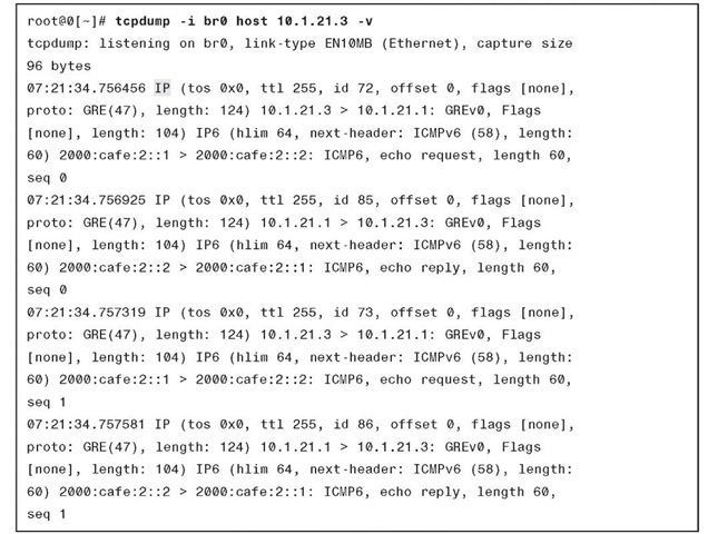
Example 3-2 shows the packet capture for the IPv6-over-IPv4 GRE tunnel. Note the presence of the IPv4 GRE HDR in front of the IPv6 packet.
Example 3-2 tcpdump Output—IPv6-over-IPv4 GRE Tunnel
The limitation of IPv6-over-IPv4 GRE tunnels is that as you add more routers and therefore more tunnels, scaling the solution becomes tedious and time-consuming. As the number of sites increases, troubleshooting and manageability of this solution become difficult.
Tunnel Broker
Initially IPv6 networks started using the transport facilities provided by IPv4 networks using the manual tunnel configurations. Various ideas like automatically configured tunnels with IPv4-compatible addresses and 6to4 have tried to solve the manual configuration issues with automation.
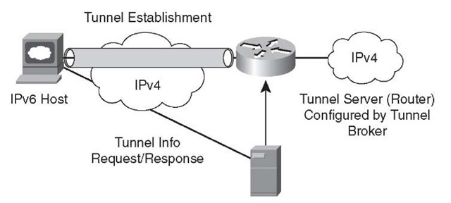
The tunnel broker, as described in RFC 3053, "IPv6 Tunnel Broker," is an alternative approach and uses the dedicated servers to simplify the establishment of tunnels, these servers are called tunnel brokers. The tunnel broker is responsible for the management of the tunnel requests coming from the endpoints. This method fits in scenarios with small, isolated IPv6 sites or IPv6 hosts. These small sites of segregated hosts are interconnected using today’s existing IPv4-based infrastructure. Applications on the remote dual-stack systems can access the IPv6 backbone by enabling tunnel broker service.
Figure 3-6 shows the automatic tunnel establishment with a tunnel broker.
Figure 3-6 Automatic Tunnel Establishment with Tunnel Broker
The primary limitation of the tunnel broker service is that the router or tunnel broker service needs to accept a configuration change from a remote server, which might have serious security implications. For example, an enterprise could register the IPv4 address of the router with the service provider on a dedicated website. The service provider delivers a script that builds a tunnel to the IPv6 network, allocates an IPv6 address to the end system, and allocates a network prefix to the router to allow connectivity for the rest of the site. The tunnel broker manages the creation and deletion of the tunnel to the tunnel server. Mistakes or leakage of this information could cause a security exposure to the site.
