This topic covers the following subjects:
■ Multicast: This section discusses how multicast is configured in IPv6. Multicast addressing introduces the effectiveness of the IPv6 addressing format. Different IPv6 multicast routing methods is also discussed in this section.
■ Quality of service (QoS): This section highlights key differences between IPv4 and IPv6 implementations of QoS and then introduces extension headers.
■ IPv6 routing: This section discusses some of the most widely used routing protocols and describes how they can be used with IPv6.
Enterprise networks today require various network services in addition to data transmission to bring employees, customers, and business partners together. Increasing employee productivity while reducing overall costs for enterprise customers today is achieved by enabling the following network services:
■ Multicast
■ Quality of Service (QoS)
■ IPv6 routing
This topic provides an overview of these network services.
In multicast transmissions, a source sends one copy of each packet to a special address that can be used by several receivers interested in that transmission. Those sources and receivers are members of a designated multicast group and can be located anywhere on the network. Multicast-enabled network devices replicate a single copy of the packet to multiple receivers instead of each receiver having a dedicated unicast connection to the source. Using multicast to transmit video traffic reduces the overall network load and minimizes the impact on the source of the video from unnecessary replication of a common data stream. Examples of applications that take advantage of multicast include videoconferencing, corporate communications, distance learning, distribution of software, stock quotes, and news.
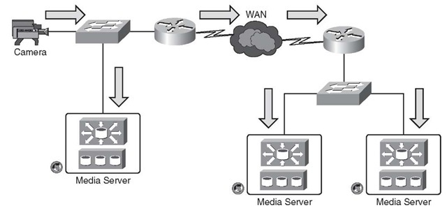
Figure 4-1 shows an example in which a single multicast stream is generated by an IP camera and archived by two or more media servers. The IP camera is the source of the multicast transmission, and the media servers are the receivers. The intermediate network components such as switches and routers replicate packets. Packets replicate only where a switch or a router needs to send the multicast stream through multiple egress ports. If unicast were to be used for this application, the IP camera would have generated three individual streams for the three media servers, resulting in unnecessary wastage of compute resources and network overhead.
Figure 4-1 Multicast Being Used for Video Surveillance
Interested receivers can be members of more than one group and must explicitly join a group before receiving content. Because multicast traffic relies on User Datagram Protocol (UDP), which, unlike TCP, has no built-in reliability mechanism such as flow control or error recovery mechanisms, tools such as QoS can improve the reliability of a multicast transmission. Some edge devices can communicate with the media server using unicast or multicast communications. The use of multicast offers some benefits when a video stream is to be archived by several media servers because only a single stream is required from the IP camera or encoder.
This topic provides a high-level overview of multicast. For a more in-depth discussion of IP multicast, refer to "Cisco IP Multicast Resources" at
http://www.cisco.com/en/US/products/ps6552/products_ios_technology_home.html.
IPv6 Multicast Addressing
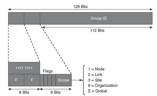
IPv6 multicast addresses are defined in RFC 4291. The IPv6 multicast address is composed of an 8-bit address, 4-bit flag, 4-bit scope, and 112-bit group ID field, as illustrated in Figure 4-2.
Figure 4-2 IPv6 Multicast Address Format
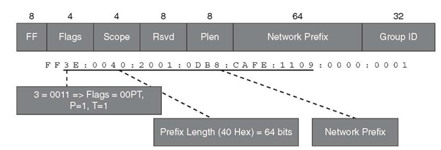
The Flags field distinguishes different address types. Bit T is defined in RFC 4291 and indicates whether the address is permanent by having a value of 0 or if the address is temporary by having a value of 1. Bit P is defined in RFC 3306 and provides a way to derive an IPv6 multicast address from an IPv6 unicast address. The example illustrated in Figure 4-3 illustrates how the RFC 3306 address is built. The Flags field when modified makes two new fields available: Plen (Prefix Length) and the network prefix that is the globally assigned IPv6 unicast prefix. This helps in the allocation of IPv6 multicast addresses, which are known and easy to manage.
Figure 4-3 Unicast Prefix Based on IPv6 Multicast Address
To further help in the allocation of IPv6 multicast addresses, RFC 3956 provides a method to embed the RP (rendezvous point) address within. Using these addresses, the only conflicting addresses would be from the same RP. This is accomplished by setting the R bit in the flags and the P and T bits to 1. This flag configuration of 0111 implies that the reserved field is only 4 bits, and the low-order 4 bits of the reserved field is now the RPAdd field. The address of the RP can be derived from the multicast address using the following two steps, as illustrated in Figure 4-4:
Figure 4-4 Embedded RP IPv6 Multicast Address
Step 1. Copy the first number of bits as defined in the Plen field from the Network Prefix field to a new 128-bit IPv6 address.
Step 2. Replace the last 4 bits with the contents of the RPAdd field.
Some IPv6 addresses are reserved by the Internet Assigned Numbers Authority (IANA). An updated list of such addresses can be found on the IANA website (http://www.iana.org); however, Table 4-1 shows a partial list of reserved addresses.
Table 4-1 List of Reserved IPv6 Multicast Addresses Registered with the IANA
|
Address |
Description |
|
ff02::1 |
All nodes on the local network |
|
ff02::2 |
All routers on the local network |
|
ff02::9 |
Routing Information Protocol (RIP) routers |
|
ff02::a |
Enhanced IGRP (EIGRP) routers |
|
ff02::d |
Protocol Independent Multicast (PIM) routers |
|
ff02::e |
Resource Reservation Protocol (RSVP) |
|
ff02::1:2 |
All Dynamic Host Configuration Protocol (DHCP) servers and relay agents on the local network site |
|
ff02::1:3 |
Link-local multicast name resolution |
Table 4-1 List of Reserved IPv6 Multicast Addresses Registered with the IANA
|
ff05::1 |
All nodes on the local network site |
|
ff05::1:3 |
All DHCP servers on the local network site |
|
ff0x::fb |
Multicast Domain Name System (DNS) |
|
ff0x::108 |
Network Information Services (NIS) |
|
ff0x::114 |
Experimental |
Multicast Listener Discovery (MLD) for IPv6
IPv6 multicast does not use the Internet Group Management Protocol (IGMP) used in IPv4 networks when a receiver signals a router with its desire to receive data from a specific group. IPv6 uses the Multicast Listener Discovery (MLD) protocol, which is a sub-protocol of Internet Control Messaging Protocol (ICMP). Table 4-2 provides a summary of MLD message types.
Table 4-2 MLD Message Types
|
Message Type |
Description |
ICMP Code |
|
Query |
General, group-specific, and multicast-address-specific. In a query message, the multicast address field is set to 0 when MLD sends a general query. The general query learns which multicast addresses have listeners on an attached link. |
130 |
|
Report |
In a report message, the multicast address field is that of the specific IPv6 multicast address to which the sender is listening. |
131 |
|
Done |
In a done message, the multicast address field is that of the specific IPv6 multicast address to which the source of the MLD message is no longer listening. |
132 |
MLD uses ICMP to carry its messages. All MLD messages are link local with a hop limit of 1, and they all have the router alert option set. The router alert option implies an implementation of the hop-by-hop option header.
An MLD report must be sent with a valid IPv6 link-local source address or an unspecified address (::) in case the sending interface has not yet acquired a valid link-local address. Sending reports with an unspecified address is allowed to support the use of IPv6 multicast in the Neighbor Discovery Protocol.
General queries (ICMPv6 type 130) are sent by the MLD querier to the all-nodes multicast group (FF02::1). Hosts/receivers will then send replies (ICMPv6 type 131) for the groups they are interested in. A reply for a group is sent to the group address. The hop limit is set to 1, and therefore the packets will never be forwarded. When a receiver wants to start receiving multicast immediately, it should immediately send a report rather than wait for the next periodical query.
When a receiver is no longer interested in a group, it sends a done message (ICMPv6 type 132). This is sent to the all-routers multicast group (FF02::2). The network device checks whether there are other receivers by sending a specific query for that address. The specific query is sent to the group address. If no hosts respond with a reply, the router then assumes that there is no more interest in the group.
Version 2 of the MLD protocol, MLDv2 as defined in RFC 3810, has additional support for source filtering. Source filtering provides the receiver with the option to report interest in listening to packets from a defined group of specific source addresses. Alternatively, source filtering also provides the option for a receiver to listen to all packets except those from a defined group of specific source addresses. MLDv2 is designed to be interoperable with MLDv1.
MLD is primarily configured in the access layer of a network (campus, branch, and data center). The network design and the L2/L3 boundary dictate where MLD is configured.
For in-depth details of MLD, refer to the RFCs in the "Additional References" section, later in this topic. You can find configuration information at the Cisco website http://www.cisco.com/go/ipv6.
Multicast Routing: Protocol Independent Multicast (PIM)
IP Protocol Independent Multicast (PIM) is the industry de facto standard for building multicast distribution trees. In most cases, the system uses the information learned from PIM to install shared-tree (*,G) and shortest-path-tree (S,G) entries in the multicast routing table.
IPv6 multicast routing is enabled with the following command:
The following are the main versions of the PIM protocols:
■ PIM Sparse Mode (PIM-SM): PIM-SM is for one/few-to-many applications, where one or multiple sources transmit to the same group. The typical applications are videoconferencing or peer-to-peer gaming. Routers must join and leave multicast groups explicitly by sending requests to the RP. Upstream routers do not forward traffic unless it has sent a join message to the RP router to receive this traffic. The RP has the responsibility of forwarding multicast data from different sources and receivers as well as serving as the root of the shared multicast delivery tree.
■ PIM Source Specific Multicast (PIM-SSM): PIM-SSM is a subset of PIM-SM and is a method of forwarding multicast traffic in which the only packets that are delivered to a receiver are those originating from a specific source address requested by the receiver. The typical applications are content delivery such as video or audio programs, including IPTV.
■ Bidirectional PIM (PIM-Bidir): PIM-Bidir was developed to help deploy emerging communication and financial applications that rely on a many-to-many applications model. PIM-Bidir is the recommended routing protocol for "hoot ‘n’ holler" applications, which enable any host to send a message to a group it belongs to.
Note PIM Dense Mode (DM) has not been implemented for IPv6.
The following sections describe each of these control plane protocols.
PIM Sparse Mode (PIM-SM)
PIM-SM for IPv6 works in the similar fashion as that of the IPv4 PIM-SM method. PIM-SM builds shared trees and requires the use of at least one rendezvous point (RP) for every multicast group. Different RPs can handle different multicast groups, and for this reason, PIM has to be complemented by a mechanism that allows routers to learn which RP to use for a given group. Such mapping mechanisms are needed both within a PIM domain and between various domains. PIM also builds a Shortest Path Tree (SPT) that is used by default for traffic forwarding.
Only IPv6 PIM provides embedded RP support. This enables the router to learn the RP address using the multicast group destination address. For routers that are the RP, the router must be statically configured as the RP. Routers learn the RP for the group from the group addresses in MLD reports or PIM messages and data packets. It can then use this RP for all PIM activity for the group.
For PIM-SM, a static RP can be configured with the following command:
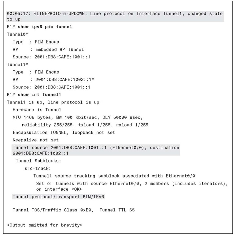
A virtual unidirectional tunnel interface can send register messages to the RP. A tunnel is automatically created for each RP configured. Example 4-1 shows the IPv6 PIM-SM configuration and virtual tunnel.
Example 4-1 IPv6 PIM-SM Configuration and Virtual Tunnel
When the network is divided into several administrative domains, it represents interdomain scenarios. IPv4-based interdomain multicast enabled each PIM domain to manage its own RP. Multicast Source Discovery Protocol (MSDP) was developed to exchange information about sources among PIM domains. Each RP would send PIM (S,G) joins to sources in other domains, provided that the RP has receivers for group G. The operation for MSDP was not scalable for many applications and hence is not supported in IPv6. Interdomain multicast in IPv6 now concentrates around PIM-SSM, discussed in the next section.
IM Source Specific Multicast (PIM-SSM)
PIM-SSM represents a subset of PIM-SM. In this case, the listener knows a priority of both the group and the source (S,G) it wants to join. PIM-SSM operates similarly to PIM-SM, but it does not build a shared tree and so it does not need an RP. The listener must indicate to its designated router (DR) what (S,G) it is interested in. For this reason,
MLDv2 listener or the SSM MLDv1 mapping router support is required for a PIM-SSM deployment.
Because it builds only (S,G)s, the deployment and management of the service is much easier than for PIM-SM. Moreover, there is no need for additional protocols that help manage the RP. On the other hand, managing the distribution of source information to listeners might represent a challenge. Application layer protocols, independent of PIM, are needed to help hosts automatically discover the source of a given group. Therefore, no additional configuration is needed to configure PIM-SSM apart from mapping MLD, which is discussed in subsequent sections.
The SSM service model requires a host to specify both the multicast group it intends to join and the specific source it intends to listen to. Only MLDv2 supports this functionality on the hosts. Although SSM is a popular deployment model, MLDv2 is not commonly implemented on IPv6 stacks at the time of this writing, so a solution is necessary to make SSM work with MLDv1. This solution is called SSM mapping for MLDv1, and it operates in two modes:
■ Statically configured mapping: A source (S) is statically mapped to a given group (G) on the router. The router maps any (*,G) MLDv1 report to an (S,G) based on the configured mapping. This mapping feature is off by default on a router. It is enabled with the global command ipv6 mld ssm-map enable. The static mapping is configured with the following global commands:
The access control list ACL1 identifies the groups mapped to the source (2001:DB8:CAFE:2001::10).
■ Dynamically configured mapping: An AAAA record is configured for G in a DNS server. When the router receives an MLDv1 report for (*,G), it does a reverse DNS lookup querying for G’s record. The DNS server returns the corresponding S for G. After the SSM mapping has been enabled globally, as previously shown, the dynamic mapping option can be configured using the following commands:
In this case, the IP address of the DNS server must be configured on the router. The DNS server can be reached over IPv6 or over IPv4 in a dual-stack network.
This feature, available on Cisco routers, enables IPv6 hosts supporting only MLDv1 to receive SSM-based multicast services.
Bidirectional PIM (PIM-Bidir)
Bidirectional PIM is a more efficient method with a large number of sources and receivers. The difference with PIM-SM is that the router near the source forwards packets back up the tree toward the RP with the RP forwarding multicast using the shared tree. This eliminates the process to create SPTs, and there is no source registration process.
Only static configuration of bidirectional RPs is supported in IPv6 and can be configured as follows:
This section covers multicast at a high level and provides methods to deploy multicast using IPv6. You can find additional in-depth learning resources of multicast routing for IPv6 at http://www.cisco.com/go/ipv6.


