Numerous IPv4 routing protocols (RP) are available for finding routes between networks, and almost every one of them has an IPv6 correspondent or extension: Routing Information Protocol next-generation (RIPng), Open Shortest Path First version 3 (OSPFv3), Intermediate System-to-Intermediate System (IS-IS), and Enhanced Interior Gateway Routing Protocol (EIGRP). Although an in-depth analysis of routing protocols is beyond the scope of this topic, OSPFv3, IS-IS, EIGRPv6, and Border Gateway Protocol (BGP) are discussed in the following sections.
OSPFv3
Open Shortest Path First (OSPF) is a link-state protocol. OSPFv2 is an interior gateway protocol (IGP) used to distribute routing information between routers of a single autonomous system for IPv4 networks. The updates for IPv6 were made in OSPF version 3 (OSPFv3).
Routers running OSPF advertise link state, link prefix/mask, link weight, and other local connectivity parameters in link-state advertisements (LSA). These LSAs are flooded reliably to other routers in the network to ensure that every OSPF router has a complete and consistent view of the topology.
On broadcast and nonbroadcast multiaccess (NBMA) networks, a designated router (DR), elected during neighboring relationship establishment (Hello protocol), can help reduce the amount of control traffic necessary for this operation by acting as a relay between OSPF routers for LSAs. A backup designated router (BDR) is also elected. The BDR picks up the functions of a failed DR with no need of a new election process. See Figure 4-6.
OSPF enables sets of networks to be grouped together into regions called areas. A router maintains a topology database for each area it participates in, and the topology of an area is hidden from the rest of the autonomous system. Areas constitute a useful concept that enables a two-level routing hierarchy, a concept that helps improve scalability. Routers do not need to maintain a topology database for areas they do not belong to, which leads to a significant reduction in routing traffic. Route summarization can occur on the area borders, another way to reduce the routing traffic. See Figure 4-7 for an example of OSPF areas.
Figure 4-6 OSPF Network Types with DR and BDR Example
Figure 4-7 OSPF Areas
For securing routing distribution and installation, OSPFv2 defines fields AuType and Authentication in its protocol header (RFC 5709).
Finally, OSPF has built-in support for classless interdomain routing (CIDR). (Each route distributed by OSPF has a destination and mask.)
OSPFv3 extends OSPF to provide support for IPv6, as specified in RFC 5340. The basic mechanisms already used by OSPFv2, such as flooding, DR election, area support, SPF calculations, and so on, remain applicable to OSPFv3. Neighboring routers are still identified by the 32-bit router ID in OSPFv3. However, changes in protocol semantics between IPv4 and IPv6, and changes in the address format, have led to significant changes in OSPFv3 compared to OSPFv2.
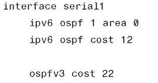
The two versions of the OSPF protocol operate independently of each other, on disjoint databases. There is no backward compatibility from OSPFv3 to OSPFv2. Example 4-2 illustrates OSPFv3 configuration using NX-OS.
Example 4-2 Unified OSPF Configuration Example on NX-OS
A main goal of OSPFv3 is to create a routing protocol that is independent of any specific network layer. To achieve this, OSPFv3′s inter-router messages have been redesigned, and addressing semantics have been removed from OSPF packets and from the basic LSAs. In OSPFv3, LSAs such as router LSAs and network LSAs carry only topology information. The following LSAs have been created to carry IPv6 addresses and prefixes:
■ Link LSAs announce the router’s IPv6 link-local address to neighbors on the link, inform these neighbors of a list of IPv6 addresses to associate with the link, and announce the set of options.
■ Intra-area prefix LSAs carry all IPv6 prefix information to all OSPFv3 routers within an area. (This information in IPv4 is carried by the router and network LSAs.)
The following LSAs have been modified:
■ Router link state advertisements and network LSAs no longer carry prefix information. In OSPFv3, these LSAs carry only topology information, making them network-protocol independent.
■ The inter-area prefix replaces the network summary or type 3 LSA. An inter-area prefix LSA advertises internal networks to routers in other areas. With IPv6, those LSAs are expressed as <prefix, prefix length> rather than <prefix, mask>.
■ The inter-area router replaces the Autonomous System Boundary Router (ASBR) summary LSA (type 4). It advertises the location of an ASBR.
OSPFv3 runs on a per-link basis rather than on a per-IP subnet basis as in OSPFv2. When OSPF peering occurs over a physical link, OSPF packets are sent using the interface link-local unicast address as source. The flooding scope for LSAs has been generalized. Authentication has been removed from the OSPF protocol itself, instead relying on IPv6′s Authentication Header (AH) and Encapsulating Security Payload (ESP). Most packets in OSPF for IPv6 are almost as compact as those in OSPF for IPv4, even with the larger IPv6 addresses.
OSPFv3 supports the ability to run multiple OSPF protocol instances on a single link. The OSPFv3 packet header includes an 8-bit instance ID used to demultiplex the protocol packets. Each OSPFv3 process sets its configured instance value in the OSPFv3 packets that it sends and ignores received packets with instance values from other OSPFv3 processes.
Instance IDs can control communication between routers sharing a physical network and OSPF area, without relying on complex authentication schemes or access lists, as needed in the past. It enables the providers to run separate OSPF routing domains, even though they have one or more physical network segments in common. For further reading, visit the IPv6 routing section at http://www.cisco.com/go/ipv6.
EIGRPv6
The Cisco-proprietary Enhanced Interior Gateway Protocol (EIGRP) was developed to bridge the gap between the traditional distance vector protocols (IGRP, RIP) and the advanced link-state protocols (OSPF, IS-IS). It integrates some of the proven capabilities of the latter to improve the operation and the scalability of the former. Nevertheless, the intent was to avoid some of the topological constraints that are sometimes associated with link-state protocols. The result is a simple yet fast-converging, resilient, and scalable routing protocol that is largely adopted in many enterprise networks and at the edge of some ISP networks.
EIGRPv6 is a distance vector routing protocol based on IGRP that offers the following improvements:
■ Diffusing update algorithm (DUAL) can determine whether a path advertised by a neighbor is loop-free and to identify alternative paths without waiting on updates from other routers.
■ It stores all routes learned, not only the best one learned from neighbors.
■ It actively queries neighbors when destinations become unreachable, and that leads to competitive convergence times.
■ It uses Hello packets to maintain neighbor state, which leads to faster convergence.
■ It uses reliable transport protocol for the exchange of updates, which eliminates the need for periodic, full updates.
■ It uses complex metrics that provide flexibility in route selection.
To meet the routing needs of enterprise networks, EIGRP has a modular design with protocol-independent core functionality and protocol-dependent modules that enable it to be used for IPv4, IPX, and AppleTalk.
The large deployed base for EIGRP drove the demand for extending its capabilities to support IPv6. The modular implementation of EIGRP simplifies the implementation. It requires the introduction of another protocol-dependent module for IPv6 (protocol identifier 88 was chosen, the same as IPv4) and three new TLVs (IPv6_REQUEST_TYPE [0X0401], IPv6_METRIC_TYPE [0X0402], and IPv6_EXTERIOR_TYPE [0X0403]).
EIGRP for IPv4 and EIGRP for IPv6 have strong similarities. A few differences exist because of some specific aspects of IPv6:
■ The router ID for the EIGRP process remains 32 bits long. It is derived from an IPv4 address found on one of the configured interfaces or is manually configured.
■ On an IPv6-only router, the EIGRP process does not start until the ID is manually configured.
■ The source address (SA) of the EIGRP Hello is the link-local address of the transmitting interface; the destination address (DA) is FF02::A (the all EIGRP routers, link-scope multicast address).
■ The format of the Hello packet implies that two neighbor routers do not have to share the same prefix on the link to see each other’s Hellos. Packets sent to specific peers are unicasted, in which case sharing the same prefix on the link becomes relevant.
■ EIGRP for IPv4 uses message digest algorithm 5 (MD5) for authentication, and similar support is provided by EIGRP for IPv6. Although not yet available at the time of this writing, support for IPsec authentication on Cisco routers is in development.
■ Automatic summarization enabled by default in EIGRP for IPv4 is disabled in EIGRP for IPv6 because IPv6 is classless.
■ Unlike EIGRP for IPv4, there is no split horizon in EIGRP for IPv6 because in IPv6, multiple prefixes could be present on the same interface of a router.
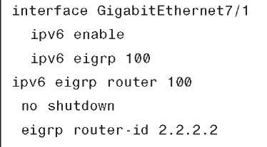
EIGRP for IPv6 will be enabled to operate within Virtual Private Networks (VPN) in a similar way as EIGRP for IPv4. Example 4-3 illustrates EIGRP for IPv6 configuration.
Example 4-3 EIGRPv6 Configuration
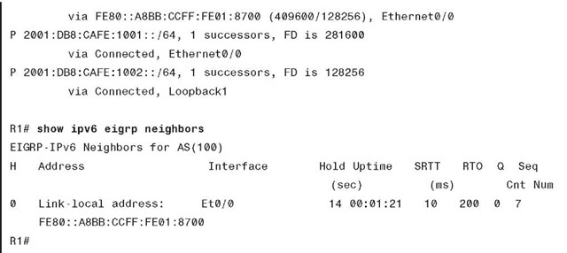
The show outputs for EIGRPv6 are similar to EIGRP, as illustrated in Example 4-4.
Example 4-4 EIGRPv6 Output
With minor syntax modifications, the commands available for tweaking or troubleshooting EIGRP for IPv4 are available for IPv6 as well.
IS-IS
The Intermediate System-to-Intermediate System (IS-IS) protocol is described in ISO Standard 10589. This link-state, OSI routing protocol was not originally developed for IP but rather to provide the routing functionality between the routers of Connectionless Network Protocol (CLNP)-based networks. With the addition of IPv4 support (RFC 1195), the protocol, sometimes referred to as Integrated IS-IS (I/IS-IS), was widely adopted as the IGP of choice for many ISP and large enterprise networks.
The implementation required a new protocol ID (0X8E) that was set to be used by the IPv6 routers to signal their capability to support ISISv6 and two new TLVs: IPv6_Reachability (0XEC) and IPv6_Interface_Address (0XE8). Extending IS-IS to support IPv6 is an exercise similar to extending it to support IPv4, unlike OSPF, where a new protocol had to be developed. For this reason, IS-ISv6 is operationally similar to IS-ISv4. Few IPv6-specific differences exist. Neighbors are listed in the adjacency table with their link-local address. Because the link-local is used in the Hello packets, adjacencies can be built between neighbors even if they do not share the same prefix. From a user perspective, a new address family was added for IPv6. Most configuration commands available for IS-ISv4 are also available for IS-ISv6 with minimal format changes.
IS-ISv6 uses a single topology and runs the same SPF calculation for all protocols supported. This mode of operation leads to certain deployment constraints. The following sections discuss single topology and multitopology.
Single Topology
By default, IS-ISv6 runs with a single topology for all protocols supported and a single instance of the SPF calculation per level (1 = area, 2 = domain). This could be a benefit because fewer resources are being used by the routers to operate it. On the other hand, the single-topology mode comes with some restrictions:
■ All routers within an area (level 1 or level 2) must support the same set of address families on all interfaces. This ensures topology consistency. It also means that the single-topology mode is not suitable in IPv4 networks where only some islands of IPv6 will be deployed.
■ The interface-configured metric applies to both IPv4 and IPv6.
This need for capabilities consistency raises this question: What will happen when an IS-ISv4 network is migrated to the IS-ISv4+IS-ISv6 network? Because routers are configured with the additional IPv6 address family, the adjacencies will be dropped until the consistency is reestablished. To avoid impacting the operating IPv4 service, you can disable the adjacency checking.
Note To avoid inconsistencies in the operational network, disable only adjacency checking during the migration process.
Multi-topology
IS-IS was enhanced to support independent topologies and SPF calculations for each protocol. In this case, various routers can support different sets of address families. To add multitopology support for IPv6, a new Multi_Topology_Reachable_IPv6_Prefixes TLV was defined. The multitopology operation can be enabled under the IPv6 address family. In this mode of operation, you can set the IPv6 metric independently of the IPv4 one.
To facilitate the migration from single topology to multitopology, you can enable a transition mode. In this case, both types of TLVs are advertised in LSPs. Larger LSPs are thus traded off for a smooth transition.
Configuring IS-ISv6
The simplest way to configure a router to run IS-IS for IPv6 is to enable the protocol on an interface with an IPv6 address. No changes are needed to the configuration of the ISIS process for IPv4, as illustrated in Example 4-5.
Example 4-5 IS-IS Configuration Example
BGP
Border Gateway Protocol version 4 (BGP4) is the exterior gateway protocol (EGP) used to exchange routes between autonomous systems in the Internet. BGP was designed based on experience gained with EGP, and provides built-in support for CIDR and route aggregation. BGP4 is specified in RFC 1771 and other BGP-related documents: RFC 1772, RFC 1773, and RFC 1774.
The BGP basic unit of routing information is the BGP path, a route to a certain set of CIDR prefixes. Paths are tagged with various path attributes, of which the most important are AS_PATH and NEXT_HOP.
The AS_PATH attribute contains a list of autonomous systems a route goes through to get to the destination. Loops are detected and avoided by checking that the router’s own ASN is not in the AS_PATHs received from neighboring autonomous systems.
The NEXT_HOP attribute is another important piece of the BGP route advertisement. When the BGP update crosses autonomous system boundaries (see the eBGP discussion that follows), the NEXT_HOP attribute is changed to be the IP address of the boundary router while, as long as updates remain within an autonomous system, the next hop is left unchanged. (See the iBGP discussion that follows.) That ensures that within the autonomous system, the next hop is always the IP address of the external peer that announced the destination prefix, and that internal BGP peers do not have to be on the path to the advertised destination.
BGP can be deployed in two forms: exterior BGP (eBGP) and interior BGP (iBGP). eBGP is used for inter-autonomous system peering, whereas iBGP carries BGP path information inside the same autonomous system. Although some of the information (route, metric) carried by iBGP might be redundant with that advertised by IGPs—such as IS-IS, OSPF, and so on—no IGP is capable of transporting BGP-specific path attributes such as the AS_PATH. Hence, iBGP is necessary to ensure that BGP path attributes received on one edge of the autonomous system, over the eBGP connection, are available on the other edge of the same autonomous system. Example 4-6 illustrates BGP configuration for advertising IPv6 network 2001:100::/24.
Example 4-6 BGP for IPv6 Configuration on IOS
The BGP routing protocol and all its IPv4-based commands work in the same manner, as illustrated in the output of the show bgp ipv6 command shown in Example 4-7.
Example 4-7 show bgp ipv6 Output
BGP runs over a TCP transport protocol. On connection start, BGP peers exchange complete copies of their routing tables. Then onward, the BGP peers maintain their respective routing database by exchanging only deltas, which makes BGP a very efficient routing protocol.
In addition to BGP attributes, CIDR is used by BGP to aggregate prefixes and reduce the size of the routing tables. When an ISP has been delegated a block of addresses, and has allocated part of this block to its own customers, BGP can aggregate routes received from these customers, and announce the entire block to its BGP peers, allowing a significant reduction in the number of BGP routing tables.
Multiprotocol BGP for IPv6
Multiprotocol BGP4 (MP-BGP), specified in RFC 4760, defines extensions enabling BGP4 to carry routing information for multiple network layer protocols.
In the most typical cases, BGP peering for announcing IPv6 routes will occur over an IPv6 transport, and eventually coexist with a separate BGP session for announcing IPv4 routes, as shown in Example 4-8.
Example 4-8 Configuring Distinct BGP Sessions for IPv4 and IPv6 Addresses
Summary
This topic provides an overview of multicast for IPv6, in which various methods of implementing multicast protocols (PIM, SSM, PIM-Bidir, and so on) were discussed.
The quality of service (QoS) section provides an overview of how to classify application packets independent of protocol version. Also, a brief comparison between IPv4 and IPv6 is provided along with an overview of extension headers.
Routing protocols such as RIPng, OSPFv3, EIGRP, ISIS, and BGP for IPv6 help in forwarding packets to their right destination. The similarities and differences between IPv4 and IPv6 are discussed for each of these protocols. IPv6 enables the network devices to cope with the growing routing tables; however, the convergence and stability are still challenges just like IPv4 and are areas for future innovations.


