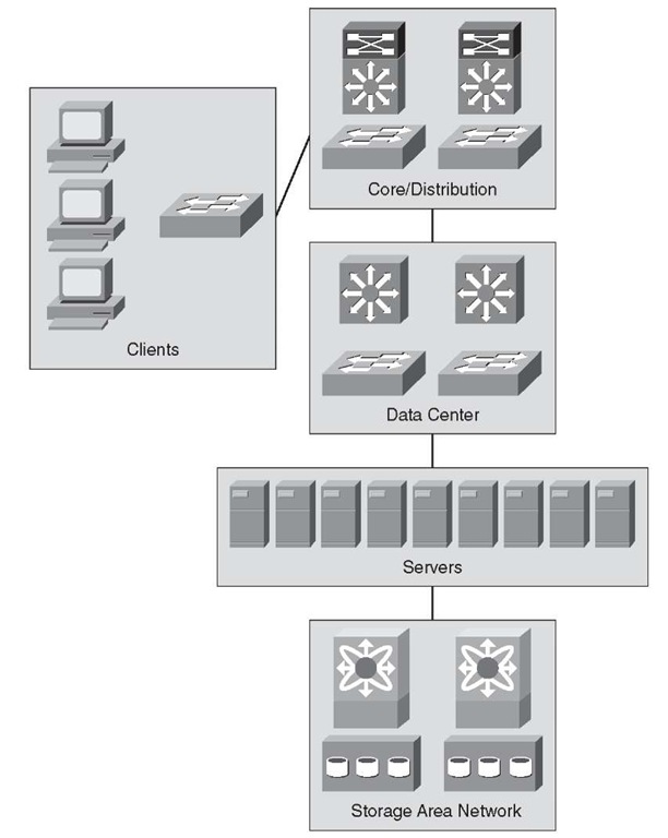
Data center design is similar to the enterprise campus with a few exceptions, such as a few features and product and performance differences. Other than those, routing is routing and switching is switching. The data center multilayered architecture consists of the following layers:
■ Aggregation layer: The aggregation layer is the termination point for the access layer and connects the data center network to the enterprise core. In many designs, enterprises consider the core to be also part of the data center, but the design principles still remain the same for the core layer. In the data center, the aggregation layer also serves as a services layer, offering Layer 4 to Layer 7 services including security (firewall), server load balancing (SLB), and monitoring services.
■ Access layer: The access layer can be a physical access layer using Catalyst and Nexus switches, or it can be virtual access layer by using a hypervisor-based software switch such as the Cisco Nexus 1000v. The access layer connects virtual machines and bare-metal servers to the network. The access layer typically connects to the servers using 10/100/1000 connectivity with uplinks to the distribution at 10 G speeds.
This architecture enables data center modules to be added as the demand and load increase.
Aggregation Layer
The aggregation layer serves as the Layer 3 and Layer 2 boundary for the data center infrastructure. The aggregation layer typically provides 10G connectivity to each access layer switch and to the enterprise core. It acts as an excellent filtering point and first layer of protection for the data center. This layer provides a building block for deploying firewall services for ingress and egress filtering. The Layer 2 and Layer 3 recommendations for the aggregation layer also provide symmetric traffic patterns to support stateful packet filtering.
In these designs, the aggregation layer (highlighted in Table 2-4) also serves as a services layer, providing L4-L7 services including security (firewalls, web application firewall [WAF]), server load balancers (SLB), and monitoring services (network analysis module [NAM]).
Table 2-4 Layers 4-7 Services in the Aggregation Layer
|
Layers 4-7 Services |
Functionality |
|
Security |
Security is often considered as an afterthought in many designs. In reality, it is easier in the long run if security is considered as part of the core requirements—and not as an add-on. Drivers for security in the data center might change over time because of new application rollouts, compliance requirements, acquisitions, and security breaches. There are three areas of focus for data center security: isolation (VLANs, VRF), policy enforcement, and physical server/virtual machine visibility. |
|
Server load balancing (SLB) |
The SLB technology abstracts the resources supporting the service to a single virtual point of contact to ensure performance and resiliency. Abstraction SLB devices mask the server’s real IP address and instead provide a single IP for clients to connect over a single or multiple protocols, including HTTP, HTTPS, and FTP. |
|
Web application firewall (WAF) |
WAF provides firewall services for web-based applications. It secures and protects web applications from common attacks, such as identity theft, data theft, application disruption, fraud, and targeted attacks. These attacks can include cross-site scripting (XSS) attacks, SQL and command injection, privilege escalation, cross-site request forgeries (CSRF), buffer overflows, cookie tampering, and DoS attacks. |
|
Monitoring |
Monitoring services are typically not integrated into the actual data flow but are integrated as passive devices to help with ongoing monitoring of flows and for debugging and troubleshooting purposes. The monitoring services can also be leveraged for capacity planning. |
Access Layer
The traditional access layer serves as a connection point for the server farm and application farms. Any communication to and from a particular server/hypervisor-based host or between hosts goes through an access switch and any associated services such as a firewall or a load balancer. There are two deployment models for server access, which are typically deployed separately:
■ End of Row (EoR): The EoR is an aggregate switch that provides connectivity to multiple racks. The EoR design typically has a single switch that aggregates multiple servers, thereby providing a single point of management.
■ Top of Rack (ToR): The ToR model has a 1/2RU switch connected within the server rack that connects to the physical servers (both 1 G and 10 G). The ToR switch has 10 G uplinks for upstream connectivity into the aggregation layer switch. Each ToR is an independent switch that needs to be managed separately for software images and configuration.
Security at the access layer is primarily focused on securing Layer 2 flows. Using VLANs to segment server traffic and associating access control lists (ACL) to prevent any unde-sired communication are best practice recommendations. Additional security mechanisms that can be deployed at the access layer include private VLANs (PVLAN) and port security features, which include IPv4 Dynamic Address Resolution Protocol (ARP) inspection, IPv6 Router Guard, and IPv6 Port Access List (IPv6 PACL). Port security can also be used to lock down a critical server to a specific port.
A virtual access layer refers to the virtual network that resides in the physical servers when configured for virtualization. Server virtualization creates new challenges for security, visibility, and policy enforcement because traffic might not leave the actual physical server and pass through a physical access switch for one virtual machine to communicate with another. Enforcing network policies in this type of environment can be a significant challenge. The goal remains to provide many of the same security services and features used in the traditional access layer in this new virtual access layer.
The virtual access layer resides in and across the physical servers running virtualization software. Virtual networking occurs within these servers to map virtual machine connectivity to that of the physical server.
Data Center Storage Network Design
Storage-area networking (SAN) is used to attach servers to remote computer storage devices such as disk arrays and tape libraries in such a way that they appear to the operating system of the servers to be locally attached devices. The growth of enterprise applications has led to an increased demand of both compute as well as storage space. The SAN offers the following benefits:
■ Application high availability: Storage is independent of applications and can be accessed through multiple paths.
■ Better application performance: Processing for data storage is offloaded from servers.
■ Consolidated storage and scalability: Simpler management, flexibility, and scalability of storage systems.
■ Disaster recovery: Data can be copied remotely using Fibre Channel over IP (FCIP) features for disaster recovery.
Historically, Fibre Channel has been used as the underlying transport technology for SAN. The Fibre Channel technology is entirely different from Ethernet and is sometimes known as "the network behind the servers." SAN has evolved from the traditional server to storage connections to include switches specially built to transport Fibre Channel Protocol (FCP) commands from one device to another. The switch is also referred to as a "fabric" in the SAN world.
As illustrated in Figure 2-6, the SAN exists independent of the Ethernet LAN. The application clients access the servers through the campus Ethernet network. The servers then use SAN for data I/O.
Figure 2-6 SAN Design
The SAN design generally fits into two distinct categories:
■ Collapsed core topology
■ Core edge topology
The next sections describe these topologies.
Collapsed Core Topology
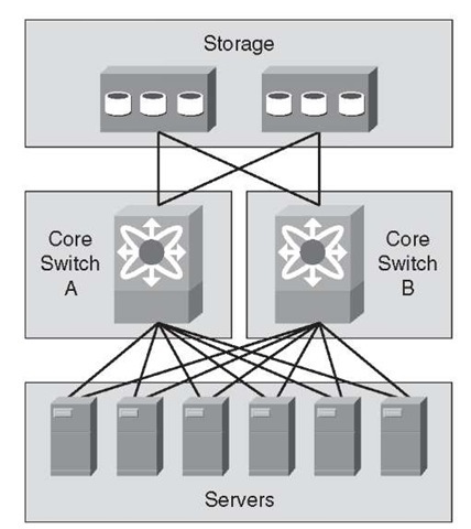
In this topology, the host server and storage devices are connected locally on a switch. Multiple switches connect in the fabric using ISLs for inters witch communications.
As the ports are filled on a switch, a new switch is added to the fabric using ISLs. The ISLs by design are used for minimal traffic between the interconnected switches because most of the traffic is local to the switches. As the fabric grows and switches are added, locality of storage is no longer feasible. This situation requires the reevaluation of the ISL bandwidth between switches because they are now more heavily used to host to storage access. Over a period of time, determining ratios for host to storage would be difficult as the fabric grows in this topology.
Figure 2-7 Collapsed Core Topology
Core Edge Topology
The core edge topology requires two redundant fabrics. Each fabric has a core switch and multiple edge switches. In the core edge architecture, the core switch supports all the storage or target ports in each fabric and ISL connectivity to the edge switches. This topology provides consolidation of storage ports at the core.
In this topology, the hosts connect to edge switches, which connect to the core through ISL trunks. Because storage is consolidated at the core switches in this topology, it can support advanced SAN features on the core switches, which eases management and reduces the complexity of the SAN. This topology also provides a deterministic host-to-storage oversubscription ratio.
Figure 2-8 Core Edge Topology
To connect islands of SANs, perhaps between data centers, technologies such as Fibre Channel over IP (FCIP) can be deployed to encapsulate Fibre Channel into IP and tunnel the traffic between fabric switches, such as the core fabric switches or other FCIP-enabled products.
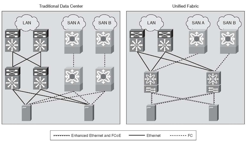
The combination of Ethernet-based LAN and storage traffic on a common lossless 10-Gigabit Ethernet network is called Unified Fabric or Unified IO. The underlying technology that enables Unified Fabric is called Fibre Channel over Ethernet (FCoE).
Currently, most environments must maintain two physically separate data center networks with completely different management tools and best practices. Moving storage traffic to Ethernet would allow the storage and user application data to flow on the same physical network.
Figure 2-9 illustrates Unified Fabric.
Figure 2-9 Unified Fabric


