This topic covers the following subjects:
■ Campus deployment models overview: A description is given of the three campus IPv6 deployment models that are most commonly used in the enterprise
■ General campus IPv6 deployment considerations: Details are provided on generic IPv6 considerations that apply to any of the three campus IPv6 deployment models
■ Implementing the dual-stack model: Detailed configuration examples are shown for the dual-stack model
■ Implementing the hybrid model: Detailed configuration examples are shown for the hybrid model
■ Implementing the service block model: Detailed configuration examples are shown for the service block
The topic breaks down IPv6 deployment into the various places in the network. This topic discusses IPv6 in the campus. The campus requirements for IPv6 are different than those in a WAN/branch environment mainly because IPv6 must be forwarded in hardware to support the high-performance requirements such as 10/100/1000 and even 10-Gbps rates commonly seen in the campus network.
When your campus Layer 3 switches cannot support IPv6 in hardware, you can use alternative designs. These options are discussed throughout this topic.
The following sections provide a high-level overview of the following three campus IPv6 deployment models and describe their benefits and applicability:
■ Dual-stack model (DSM): Both IPv4 and IPv6 are deployed simultaneously on the same interfaces.
■ Hybrid model (HM): Host-based tunneling mechanisms are used to encapsulate IPv6 in IPv4 when needed, and dual-stack is used everywhere else.
■ Service block model (SBM): This is similar to the hybrid model, only tunnel termination occurs in a purpose-built part of the network known as the service block.
Dual-Stack Model
The dual-stack model (DSM) is completely based on the dual-stack transition mechanism. An interface or link on which two protocol stacks have been enabled at the same time operates in dual-stack mode. Examples of previous uses of dual-stack include IPv4 and IPX or IPv4 and AppleTalk coexisting on the same device.
Dual-stack is the preferred, most versatile way to deploy IPv6 in existing IPv4 environments. IPv6 can be enabled wherever IPv4 is enabled, along with the associated features required to make IPv6 routable, highly available, and secure.
The tested components area of each section of this topic gives a brief view of the common requirements for the DSM to be successfully implemented. The most important consideration is to ensure that there is hardware support for IPv6 in campus network components such as switches. Within the campus network, link speeds and capacity often depend on such issues as the number of users, types of applications, and latency expectations. Because of the typically high data rate requirements in this environment, Cisco does not recommend enabling IPv6 unicast or multicast layer switching on software for-warding-only platforms. It is important to understand that you can have a platform that can perform IPv4 forwarding in hardware, yet IPv6 forwarding is done in software. Enabling IPv6 on software forwarding-only campus switching platforms can be suitable in a test environment or a small pilot network, but certainly not in a production campus network. It is critical to take an inventory of your campus switching products to ensure that you can perform IPv6 in hardware.
The following section highlights some of the benefits and drawbacks of the DSM and introduces the high-level topology and tested components.
Benefits and Drawbacks of the DSM
Deploying IPv6 in the campus using DSM offers several advantages over the hybrid and service block models. The primary advantage of DSM is that it does not require tunneling within the campus network. DSM runs the two protocols as "ships in the night," meaning that IPv4 and IPv6 run alongside one another and have no dependency on each other to function, except that they share network resources. Both IPv4 and IPv6 have independent routing, high availability (HA), quality of service (QoS), security, and multicast policies. Dual-stack also offers processing performance advantages because packets are natively forwarded without having to account for additional encapsulation and lookup overhead.
Note Customers who plan to or have already deployed the Cisco routed access design will fill find that IPv6 is also supported within that same design.
The primary drawback to DSM is that network equipment upgrades might be required when the existing network devices are not IPv6 capable. Also, there is an operational cost in operating two protocols simultaneously because there are two sets of everything, such as addressing, routing protocols, access control lists (ACL), management, and so on.
DSM Topology
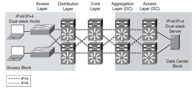
Figure 6-1 shows a high-level view of the DSM-based deployment in campus networks. The environment is using a traditional three-tier design, with an access, distribution, and core layer in the campus. All relevant interfaces that have IPv4 enabled also have IPv6 enabled, making it a true dual-stack configuration. This example is the basis for the detailed configurations that are presented later in this topic.
Figure 6-1 Dual-Stack Model Example
Note The data center block is shown here for reference only and is not discussed in this topic.
DSM-Tested Components
Table 6-1 lists the components that were used and tested in the DSM configuration.
Hybrid Model
The hybrid model (HM) strategy is to employ two or more independent transition mechanisms with the same deployment design goals. Flexibility is the key aspect of the hybrid approach, in which any combination of transition mechanisms can be leveraged to best fit a given network environment.
Table 6-1 DSM-Tested Components
|
Campus Layer |
Hardware |
Software |
|
Access layer |
Cisco Catalyst 3750E/3560E Catalyst 4500 Supervisor 6-E Catalyst 6500 Supervisor 32 or 720 |
12.2(46)SE 12.2(46)SG 12.2(33)SXI |
|
Host devices |
Various laptops: PC and Apple |
Microsoft Windows XP, Windows Vista, Windows 7, Apple Mac OS X, and Red Hat Enterprise Linux WS |
|
Distribution layer |
Catalyst 4500 Supervisor 6-E Catalyst 6500 Supervisor 32 or 720 |
12.2(46)SG 12.2(33)SXI |
|
Core layer |
Catalyst 6500 Supervisor 720 |
12.2(33)SXI |
The HM adapts as much as possible to the characteristics of the existing network infrastructure. Transition mechanisms are selected based on multiple criteria, such as IPv6 hardware capabilities of the network elements, number of hosts, types of applications, location of IPv6 services, and network infrastructure and end system operating system feature support for various transition mechanisms.
The HM leverages the following three main IPv6 transition mechanisms:
■ Dual-stack: Deployment of two protocol stacks: IPv4 and IPv6
■ Intra-Site Automatic Tunnel Addressing Protocol (ISATAP): Host-to-router tunneling mechanism that relies on an existing IPv4-enabled infrastructure
■ Manually configured tunnels: Router-to-router tunneling mechanism that relies on an existing IPv4-enabled infrastructure
The HM provides hosts with access to IPv6 services, even when the underlying network infrastructure might not support IPv6 natively.
The key aspect of the HM is that hosts located in the campus access layer can use IPv6 services when the distribution layer is not IPv6-capable or enabled. The distribution layer switch is most commonly the first Layer 3 gateway for the access layer devices. If IPv6 capabilities are not present in the existing distribution layer switches, the hosts cannot gain access to IPv6 addressing (stateless autoconfiguration or DHCP for IPv6) and router information, and subsequently cannot access the rest of the IPv6-enabled network.
Tunneling can be used on the IPv6-enabled hosts to provide access to IPv6 services located beyond the distribution layer. HM leverages the ISATAP tunneling mechanisms on the hosts in the access layer to provide IPv6 addressing and off-link routing. Microsoft Windows XP, Windows Vista, and Windows 7 hosts in the access layer need to have IPv6 enabled and either a static ISATAP router definition or DNS "A" record entry configured for the ISATAP router address.
Note The configuration details are shown in the section "Implementing the Hybrid Model," later in this topic.
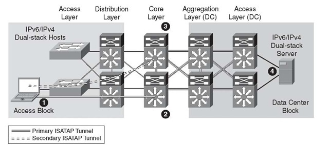
Figure 6-2 shows the basic connectivity flow for the HM.
Figure 6-2 Hybrid Model – Connectivity Flow
The following list describes the four steps in the HM connectivity flow shown in Figure 6-2:
Step 1. The host establishes an ISATAP tunnel to the core layer.
Step 2. The core layer switches are configured with ISATAP tunnel interfaces and are the termination point for ISATAP tunnels established by the hosts. As you can see, this is not ideal because the core layer is designed to be very streamlined and to perform packet forwarding only; it is not a tunnel termination point.
Step 3. Pairs of core layer switches are redundantly configured to accept ISATAP tunnel connections to provide high availability of the ISATAP tunnels. Redundancy is available by configuring both core layer switches with loop-back interfaces that share the same IPv4 address. Both switches use this redundant IPv4 address as the tunnel source for ISATAP. When the host connects to the IPv4 ISATAP router address, it connects to one of the two switches (this can be load balanced or be configured to have a preference for one switch over the other). If one switch fails, the IPv4 Interior Gateway Protocol (IGP) converges and uses the other switch, which has the same IPv4 ISATAP address as the primary. The failover takes as long as the IGP convergence time plus the Neighbor Unreachability Detection (NUD) time expiry. More information on NUD can be found in RFC 4861, "Neighbor Discovery for IP version 6 (IPv6)." With Microsoft Windows Vista and Windows 7 configurations, basic load balancing of the ISATAP routers (core switches) can be implemented. For more information on the Microsoft implementation of ISA-TAP on Windows platforms, see the white paper "Manageable Transition to IPv6 using ISATAP," which is available at the Microsoft Download Center: http://tinyurl.com/2jhdbw.
Step 4. The dual-stack configured server accepts incoming connection requests and/or establishes outgoing IPv6 connections using the directly accessible dual-stack-enabled data center block.
Many customers simply configure one ISATAP interface for all of their users within the network. This works, but you lose the ability to have control over traffic based on source IPv4 address information.
To help control where ISATAP tunnels can be terminated and what resources the hosts can reach over IPv6, you can use VLAN or IPv4 subnet-to-ISATAP tunnel matching. If the current network design has a specific VLAN associated with ports on an access layer switch and the users attached to that switch are receiving IPv4 addressing based on the VLAN to which they belong, a similar mapping can be done with IPv6 and ISATAP tunnels.
Figure 6-3 illustrates the process of matching users in a specific VLAN and IPv4 subnet with a specific ISATAP tunnel.
Figure 6-3 Hybrid Model – ISATAP Tunnel Mapping
The following list describes the ISATAP tunnel mapping and numbered icons shown in Figure 6-3:
Step 1. The core layer switch is configured with a loopback interface with the address of 10.122.10.2, which is used as the tunnel source for ISATAP, and is used only by users located on VLAN 2 (that is, the 10.120.2.0/24 subnet).
Step 2. The host in the access layer is connected to a port that is associated with a specific VLAN. In this example, the VLAN is VLAN-2. The host in VLAN-2 is associated with an IPv4 subnet range (10.120.2.0/24) in the DHCP server configuration.
The host is also configured for ISATAP and has been statically assigned the ISATAP router value of 10.122.10.2. This static assignment can be implemented in several ways. An ISATAP router setting can be defined through a command on the host (netsh interface ipv6 isatap set router 10.122.10.2—details provided in the "Tunnel Configuration" section, later in the topic), which can be manually entered or scripted through Microsoft PowerShell, Microsoft SMS Server, Group Policy, or a number of other scripting methods. The script can determine to which value to set the ISATAP router by examining the existing IPv4 address of the host. For example, the script can analyze the host IPv4 address and determine that the value "2" in the 10.120.2.x/24 address signifies the subnet value. The script can then apply the command using the ISATAP router address of 10.122.10.2, where the "2" signifies subnet or VLAN 2. The 10.122.10.2 address is actually a loopback address on the core layer switch and is used as the tunnel endpoint for ISATAP.
Note You can find configuration details in the section "Implementing the Hybrid Model," later in this topic.
A customer might want to provide separate tunnel loopbacks for the following reasons:
■ Control and separation: If a security policy is in place that disallows certain IPv4 subnets from accessing a specific resource, and access control lists (ACL) are used to enforce the policy, what happens if HM is implemented without consideration for this policy? If the restricted resources are also IPv6 accessible, those users who were previously disallowed access through IPv4 can now access the protected resource through IPv6. If hundreds or thousands of users are configured for ISATAP and a single ISATAP tunnel interface is used on the core layer device (or wherever the termination point is), controlling the source addresses through ACLs would be very difficult to scale and manage. If the users are logically separated into ISATAP tunnels in the same way they are separated by VLANs and IPv4 subnets, ACLs can be easily deployed to permit or deny access based on the IPv6 source, source/destination, and even Layer 4 information.
■ Scale: For years, it has been a best practice to control the number of devices within each single VLAN of the campus networks. This practice has traditionally been enforced for broadcast domain control. Although IPv6 and ISATAP tunnels do not use broadcast, there are still scalability considerations to think about. These include control plane impact of encapsulation/decapsulation, line rate performance of tunneled traffic, and so on. The good news is that the Cisco Catalyst 6500 with Supervisor 720 and Supervisor 32G perform ISATAP tunneling in hardware.
The following are the main solution requirements for HM strategies:
■ IPv6 and ISATAP support on the operating system of the host machines
■ IPv6/IPv4 dual-stack and ISATAP feature support on the core layer switches
As mentioned previously, numerous combinations of transition mechanisms can be used to provide IPv6 connectivity within the enterprise campus environment, such as the following two alternatives to the previous requirements:
■ Using 6to4 tunneling instead of ISATAP if multiple host operating systems such as Linux, FreeBSD, Sun Solaris, and MAC OS X are used within the access layer
■ Terminating tunnels at a network layer different than the core layer, such as the data center aggregation layer
Note The 6to4 and non-core-layer alternatives are not discussed in this topic and are listed only as secondary options to the deployment recommendations for the HM. There are additional considerations with 6to4 because the design, security, and scale components do change.
Benefits and Drawbacks of the HM
The primary benefit of the HM is that the existing network equipment can be leveraged without the need for upgrades, especially the distribution layer switches. If the distribution layer switches currently provide acceptable IPv4 service and performance and are still within the depreciation window, the HM can be a suitable choice.
It is important to understand the drawbacks of the hybrid model:
■ IPv6 multicast is not supported within ISATAP tunnels.
■ Terminating ISATAP tunnels in the core layer makes the core layer appear as an access layer to the IPv6 traffic. Network administrators and network architects design the core layer to be highly optimized for the role it plays in the network, which is often to be stable, simple, and fast. Adding a new level of intelligence to the core layer might not be acceptable.
■ Granular VLAN or IPv4 subnet-to-ISATAP tunnel mapping can introduce a lot of operational overhead through a tremendous amount of configuration. You should land somewhere between a single ISATAP tunnel interface for the entire organization and the granular mapping examples discussed in this topic. Your goal should be to deploy enough ISATAP isolation to meet your needs without it becoming too much to maintain. Dual-stack should be pursued aggressively to relieve the HM overhead.
As with any design that uses tunneling, considerations that must be accounted for include performance, management, security, scalability, path MTU, and availability. The use of tunnels is always a secondary recommendation to the DSM design.
HM Topology
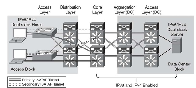
Figure 6-4 shows a high-level view of the campus HM. ISATAP tunnels are established from hosts in the access layer and terminate on the core layer switches. The solid lines indicate the primary tunnel. If the core layer switch that terminates the primary tunnel fails, the host will reestablish the tunnel to the other core layer switch. ISATAP high availability will be discussed in detail later in this topic. This example is the basis for the detailed configurations that follow later in this topic.
Figure 6-4 Hybrid Model Topology
HM-Tested Components
The following are the components used and tested in the HM configuration:
■ Campus layer: Core layer
■ Hardware: Catalyst 6500 Supervisor 720
■ Software: 12.2(33)SXI
Note that the only Cisco Catalyst components that need to have IPv6 capabilities are those terminating ISATAP connections and the dual-stack links in the data center. Therefore, the software versions in the campus access and distribution layer roles are not relevant to this design.
Service Block Model
The service block model (SBM) is significantly different compared to the other campus models discussed in this topic. Although the concept of a service block design is not new, the SBM does offer unique capabilities to customers facing the challenge of providing access to IPv6 services in a short time frame. A service block approach has also been used in other design areas such as Cisco Network Virtualization, which refers to this concept as the services edge. The SBM is unique in that it can be deployed as an overlay network without any impact to the existing IPv4 network, and it is completely centralized. This overlay network can be implemented rapidly while allowing high availability of IPv6 services, QoS capabilities, and restriction of access to IPv6 resources with little or no changes to the existing IPv4 network.
As the existing campus network becomes IPv6 capable, the SBM can become decentralized. Connections into the SBM are changed from tunnels (ISATAP and/or manually configured) to dual-stack connections. When all the campus layers are dual-stack capable, the SBM can be dismantled and repurposed for other uses.
The SBM deployment is based on a redundant pair of Catalyst 6500 switches with a Supervisor 32 or Supervisor 720. If the SBM is being deployed in a pilot, lab, or small production environment, Cisco ISR or other Cisco Software forwarding-based routers can act as the termination device. The key to maintaining a highly scalable and redundant configuration in the SBM is to ensure that a high-performance switch, supervisor, and modules are used to handle the load of the ISATAP, manually configured tunnels, and dual-stack connections for an entire campus network. As the number of tunnels and required throughput increase, it might be necessary to distribute the load across an additional pair of switches in the SBM.
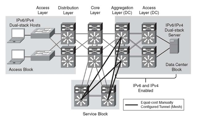
There are a few similarities between the SBM example given in this topic and the hybrid model. The underlying IPv4 network is used as the foundation for the overlay IPv6 network being deployed. ISATAP provides access to hosts in the access layer, similar to the hybrid model. Manually configured tunnels are used from the data center aggregation layer to provide IPv6 access to the applications and services located in the data center access layer. IPv4 routing is configured between the core layer and SBM switches to allow visibility to the SBM switches for the purpose of terminating IPv6-in-IPv4 tunnels. In the example discussed in this topic, however, the extreme case is analyzed where there are no IPv6 capabilities anywhere in the campus network (access, distribution, or core layers). The SBM example used in this topic has the switches directly connected to the core layer through redundant high-speed links.
Benefits and Drawbacks of the SBM
From a high-level perspective, the advantages to implementing the SBM are the pace of IPv6 services delivery to the hosts, the lesser impact on the existing network configuration (no termination of tunnels, command-line entries), and the flexibility of controlling the access to IPv6-enabled applications.
In essence, the SBM provides control over the pace of IPv6 service rollout by leveraging the following:
■ Configuring per-user and/or per-VLAN tunnels through ISATAP to control the flow of connections and allow the measurement of IPv6 traffic use by allowing interface-specific monitoring and specific source/destination pairing in network monitoring tools such as in NetFlow.
■ Controlling access on a per-server or per-application basis through ACLs and/or routing policies at the SBM. This level of control allows access to one, a few, or even many IPv6-enabled services while all other services remain on IPv4 until those services can be upgraded or replaced. This setup enables a "per-service" deployment of IPv6.
■ Allowing high availability of ISATAP and manually configured tunnels as well as all dual-stack connections.
■ Allowing hosts access to the IPv6-enabled Internet service provider (ISP) connections, either by allowing a segregated IPv6 connection used only for IPv6-based Internet traffic or by providing links to the existing Internet edge connections that have both IPv4 and IPv6 ISP connections.
■ Implementing the SBM does not disrupt the existing network infrastructure and services.
As mentioned in the case of the hybrid model, there are drawbacks to any design that relies on tunneling mechanisms as the primary way to provide access to services. The SBM not only suffers from the same drawbacks as the HM design (lots of tunneling), but it also adds the cost of additional equipment not found in the HM. More switches (the SBM switches) and line cards are needed to connect the SBM and core layer switches, and any maintenance or software required represents additional expenses.
Because of the list of drawbacks for the HM and SBM, Cisco recommends to always aim for dual-stack deployment.
SBM Topology
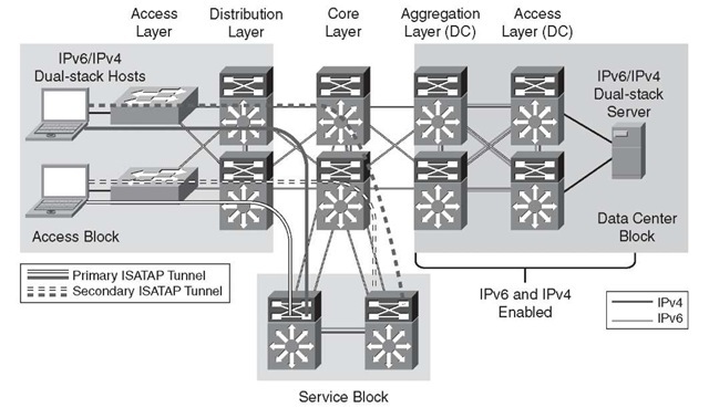
Two portions of the SBM design are discussed in this topic. Figure 6-5 shows the ISA-TAP portion of the design, and Figure 6-6 shows the manually configured tunnel portion of the design. These views are just two of the many combinations that can be generated in a campus network and differentiated based on the goals of the IPv6 design and the capabilities of the platforms and software in the campus infrastructure.
Figure 6-5 shows the redundant ISATAP tunnels coming from the hosts in the access layer to the SBM switches. The SBM switches are connected to the rest of the campus network by linking directly to the core layer switches through IPv4-enabled links. The SBM switches are connected to each other through a dual-stack connection that is used for IPv4 and IPv6 routing and HA purposes.
Figure 6-6 shows the redundant, manually configured tunnels connecting the data center aggregation layer and the service block. It is also common to see servers in the data center use ISATAP to connect to either the HM or SBM termination points. Hosts located in the access layer can now reach IPv6 services in the data center access layer using IPv6. Refer to the section "Implementing the Service Block Model," later in this topic, for the details of the configuration.
Figure 6-5 Service Block Model – Connecting the Hosts (ISATAP Layout)
Figure 6-6 Service Block Model – Connecting the Data Center (Manually Configured Tunnel Layout)
SBM-Tested Components
The following are the components used and tested in the SBM configuration:
■ Campus layer: Core layer
■ Hardware: Catalyst 6500 Supervisor 720
■ Software: 12.2(33)SXI
