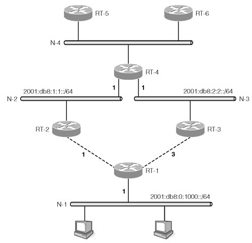
The RIPng protocol is based on the distance-vector algorithm commonly known as the Bellman-Ford algorithm. Consider the example in Figure 1-8. Router RT-1 advertises its directly connected network N-1 of prefix 2001:db8:0:1000::/64 with a metric of 1 on the point-to-point links to RT-2 and RT-3. The costs of the links from RT-1 to RT-2 and RT-3 are 1 and 3 respectively, which have RT-2 and RT-3 advertise the same prefix on networks N-2 and N-3 (where router RT-4 resides) but with different metrics. RT-2 advertises a metric value of 2 while RT-3 advertises a metric value of 4. After processing the routing messages from RT-2 and RT-3, RT-4 selects the route with the smaller metric and chooses RT-2 as the next hop to reach network 2001:db8:0:1000::/64 with a metric of 2.
FIGURE 1-8
RT-4 adds the cost of its network to the received metric and advertises that prefix with a metric of 3 on network N-4. RT-4 also advertises prefixes 2 0 01 :db8:1:1::/64 and 2001 :db8:2:2::/64 for networks N-2 and N-3 on N-4. RT-5 and RT-6 receive this routing information and build their routing tables.
We can see from this example that RT-4 is able to compute the optimal route to prefix 2001:db8:0:1000::/64 from just the information exchanged with RT-2 and RT-3. The direction going toward this network is through RT-2.
RIPng Message Formats
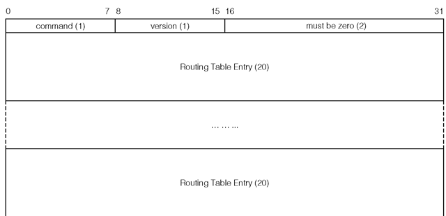
Figure 1-9 depicts the RIPng protocol message format. Each decimal value in parentheses refers to the field size in bytes. command This field specifies whether the RIPng message is a request message or a response message. A value of 1 indicates a request message, a value of 2 indicates a response message.
The next two bytes must be set to zero by the sender.
Each Routing Table Entry (RTE) field is 20 bytes in size and specifies a reachable IPv6 destination. The format of the RTE field is shown in Figure 1-10.
IPv6 prefix The IPv6 prefix is 16 bytes in size and specifies either an IPv6 network or an IPv6 end node depending on the prefix length. The prefix is stored in network byte order.
FIGURE 1-9
FIGURE 1-10
FIGURE 1-11
The route tag was designed for distinguishing the origin of the route, that is, whether the advertised prefix was imported from another routing protocol. In practice the route tag is used by operators to define sets of routes for custom handling in RIPng. The receiving router must preserve this field and readvertise it with the prefix.
Prefix length The prefix length specifies the number of significant bits of the prefix field, counting from left to right. The valid prefix length is 0 to 128 inclusive. The prefix field is ignored if the prefix length is 0, which indicates that the advertised route is a default route. In this case it is good practice to set the prefix field to 0:0:0:0:0:0:0:0, or :: in compressed form.
Metric Even though the metric field is 1 byte in size, the valid values are 0 to 15, which specifies the cost of reaching the advertised destination. Value 16, known as infinity, indicates the advertised destination is not reachable. We will revisit the infinity value in Section 1.4.2.
In general the receiving router sets the advertising router as the next hop for the advertised destination. The advertising router may optionally specify a next hop router for one or more destinations by a special RTE. Figure 1-11 illustrates the special RTE that is used for specifying a next hop address.
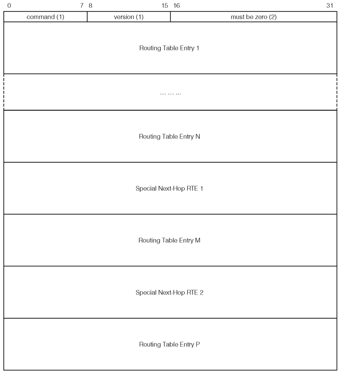
The IPv6 next hop address field contains a link-local address of the next hop router, which belongs to the interface that shares the same network segment as the advertising router. The metric field is set to 0xFF. If the next hop address is :: , then the originating router of the message is used as the next hop router. If the next hop address is not a link-local address, then again the originating router is used as the next hop router. All of the RTEs that follow this special RTE will use the given address as the next hop router until either another special RTE is encountered, or the end of the message is reached. For example, consider Figure 1-12.
In this example, the advertising router is treated as the next hop router for RTE 1 to N. The next hop router specified in the special RTE 1 applies to destination M, and the next hop router specified in the second special RTE applies to destination P.
FIGURE 1-12
The number of RTEs that can be carried in a single RIPng message is limited by the link MTU. The formula for calculating the number of RTEs is given as:
RIPng Operation
The RIPng protocol operates over UDP. The IANA assigned port number for the RIPng process is 521.
A router sends its entire routing table to all its directly connected neighboring routers every 30 seconds—called a regular update. This unsolicited transmission has a UDP source port 521 and a destination port 521. The source address must be a link-local address of the transmitting interface of the originating router. The destination address is the all-rip-routers multicast address ff02::9.
When a router first comes up and is in the initialization phase, it may request other routers to send their routing tables in order for it to populate its routing table. This request may be sent to the all-rip-routers multicast address on each attached interface. If there exists only a single RTE in the RIPng request message, and the prefix in this RTE is ::, the prefix length is 0, and the metric value is 16, then the requesting router is asking the receiving router to send its entire routing table.
A router may send a request to a specific peer soliciting a specific list of destinations. In this case, the receiving router processes each RTE by performing a search of the given prefix in its routing table. If an entry is found, then the metric value is retrieved and is set in the RTE. If an entry is not found, then the metric value is set to 16 indicating the destination is not reachable from this router’s perspective. Once all of the RTEs have been processed, the command field is changed from request to response and is sent to the requesting router.
When a router receives a message from a neighbor, if it contains a destination that is not already in its routing table, or if either the metric or the next hop address of an existing route entry is updated by the newly received RTE, then the corresponding route entry in the routing table is created or updated with new information. The next hop address of the entry is set to the source address of the received message or the next hop address specified by a next hop RTE (shown in Figure 1-11); note that in either case the address is a link-local address. The receiving router will then send an update message on all other interfaces. This process is called a triggered update, and is limited to one transmission per 1 to 5 seconds, depending on the timer expiration.
There are two timers associated with each route entry: the timeout timer and the garbage collection timer. The timeout timer is initialized to 180 seconds when the route entry is first created. Each time a response message which contains the destination of this route entry is received, the timeout timer is reset to 180 seconds. The route entry is considered expired if a message has not been received which covers that destination. In this case, once the route entry expires, a garbage collection timer is initialized to 120 seconds for the expired entry. The route entry is removed from the routing table when the garbage collection timer expires. The reason for setting the garbage collection timer is to aid convergence, as explained in Section 1.4.3.
The following points summarize the key characteristics of the RIPng protocol:
• The routing algorithm selects a best route for each possible destination using distance as the main selection criteria.
• Each piece of routing information consists of a destination, a gateway and the distance to the destination.
• A router exchanges routing information with only directly connected routers. Route information from a new neighboring router can be dynamically reflected, but the state of each router is not maintained.
• Distribution of routing information is unreliable because the routing information is exchanged over UDP without any application-level acknowledgments.
• Origin of a route cannot be identified.
• Route computation is distributed in that selection decision made at one router depends largely on the route selection decisions made by other routers.
• Routing loop cannot always be detected or avoided.
• The algorithm can be vulnerable to topological changes and can converge slowly.
Problems with RIPng
The main advantage of RIPng is that RIPng is a simple routing protocol and its implementation is fairly straightforward. This simplicity, however, causes a number of operational problems. The most visible problems are its inability to detect routing loops in more complex network topologies and that it may converge slowly in some situations. This was briefly discussed in Section 1.3.1; this section revisits and details the problem in the context of the RIPng protocol. Consider the example given in Figure 1-13.
In this figure, the horizontal axis represents time. The first vertical column lists the available routers RT-1, RT-2 and RT-3. Starting from the second column, each pair of values represents each router’s perspective on the reachability of the IPv6 prefix 2001:db8:0:1000/64, that is, the gateway to the prefix and the cost of that path. For example, at time ti, RT-1 sees the prefix 2001 :db8 : 0 : 1000 ::/64 as directly reachable, and the cost of that route is 1. At the same time, router RT-2 and RT-3 view the prefix as reachable through router RT-1, and the costs of the route are 2 and 4 respectively.
Router RT-1 advertises network 2001:db8:0:1000::/64 to both RT-2 and RT-3 with metric 1. At time t2, the link between RT-1 and N-1 is broken. This link is the only one to reach N-1. Now RT-1 correctly marks 2001 :db8 : 0 : 1000 ::/64 as unreachable. However, at time t3 both RT-2 and RT-3 still advertise a route to 2001:db8:0:1000::/64 with metric 2 and 4 respectively. At time t4, upon receiving these routes from RT-2 and RT-3, RT-1 incorrectly thinks that N-1 is reachable through either RT-2 or RT-3. Since RT-2 advertises a smaller metric, RT-1 treats RT-2 as the next hop router and inserts the route with the updated metric 3 into its routing table. This route entry is then advertised to RT-2 and RT-3 causing both RT-2 and RT-3 to think N-1 is now reachable via RT-1 but with a new metric value. RT-2 and RT-3 update their metric values accordingly and readvertise the route to RT-1. RT-1 again updates its metric value and then advertises the update route back to RT-2 and RT-3. This process continues until eventually all three routers have a metric value of 16 to 2001:db8:0:1000::/64, which indicates this network is no longer reachable, that is, this is a symptom of the counting to infinity problem described in Section 1.3.1.
FIGURE 1-10
With the counting to infinity problem, none of the routers would know that N-1 is no longer reachable until the metric value reaches 16 at a time long passed t2, (i.e., at time tn). One reason that the metric for RIPng has a maximum allowed value of 16 is that the larger the allowable metric, the longer RIPng takes to reach the convergence state. The maximum value of 16 also implies that RIPng is limited to networks that have diameters of at most 15 hops, assuming the cost of each hop is 1. Note in this example, RT-3 converges faster than both RT-1 and RT-2 due to its larger metric value.
As illustrated by this example, due to the counting to infinity problem, RIPng has a large convergence time when it is deployed in more complex networks. As can be seen from this example, the source of the problem is that RT-2 is advertising to RT-1 a route which RT-2 had learned from RT-1. The problem disappears if RT-2 never advertises any route that was learned from RT-1 back to RT-1. This solution is called the Split Horizon algorithm. Alternatively, RT-2 may advertise the route that it learned from RT-1 back to RT-1, but RT-2 sets the metric to 16 which indicates that destination is not reachable through RT-2, which is known as route poisoning. The garbage collection timer mentioned in the pevious section, also known as the hold-down timer, is used for route poisoning. During the hold-down time, an expired route is advertised to the neighbors with a metric of 16. Split horizon combined with route poisoning is called Split Horizon with Poisoned Reverse.
FIGURE 1-10
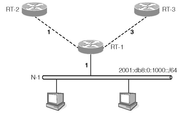
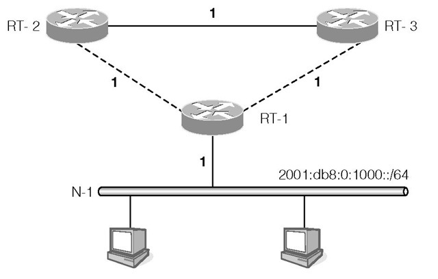
The Split Horizon algorithm solves the problem depicted in Figure 1-13, but this algorithm still cannot detect the routing loop if the network has a configuration as shown in Figure 1-14.
In this figure, because RT-2 and RT-3 share a common link, the two routers will advertise 2001:db8:0:1000::/64 with a metric of 2 to each other. Due to Split Horizon with Poisoned Reverse, RT-2 and RT-3 both advertise to RT-1 that 2 0 01 :db8 :0:1000::/64 is unreachable. When the link between RT-1 and N-1 is broken, RT-1 will mark N-1 as unreachable. At this point RT-2 considers the new route to 2001:db8:0:1000::/64 is through RT-3 with a metric of 3. RT-2 will also advertise this route to RT-1. RT-1 is led to believe that 2001:db8:0:1000::/64 is now reachable through RT-2. Again the counting to infinity problem occurs and the Split Horizon algorithm could not detect the routing loop in this configuration.
