Router-LSA
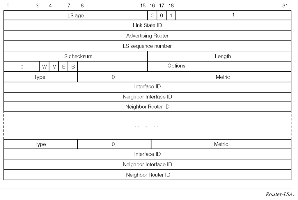
Figure 1-31 shows the format of the Router-LSA.
W The W-bit is used by Multicast OSPF and is not discussed in this topic.
V The V-bit identifies the advertising router as an endpoint of at least one virtual link over a transit area.
E The E-bit identifies the advertising router as an ASBR.
B The B-bit identifies the advertising router as an ABR.
Options This field describes the advertising router’s capabilities. Figure 1-27 shows the structure of this field. The advertising router describes each of its active attached interfaces using the Type, Metric, Interface ID, Neighbor Interface ID, and the Neighbor Router ID fields. One set of these fields is used for each interface.
Type This field identifies the type of the interface. The values and the interface types these values represent are as follows:
1 a point-to-point interface
2 connection to a transit network
3 reserved
4 virtual link
FIGURE 1-31
Metric This field specifies the cost of using the described interface for outbound traffic.
Interface ID The interface ID is assigned by the advertising router, which uniquely identifies an interface within that router.
Neighbor Interface ID This field identifies the interface ID of the neighboring router that shares the same link as the advertising router. For a Type 2 interface the Neighbor Interface ID stores the interface ID of the DR on the transit network.
Neighbor Router ID This field contains the router ID of the neighboring router. For a Type 2 interface this router ID stores the router ID of the DR on the transit network. For Type 2 links, the combination of the Neighbor Interface ID and the Neighbor Router ID uniquely identifies the Network-LSA advertised for the attached link in the LSDB.
Network-LSA
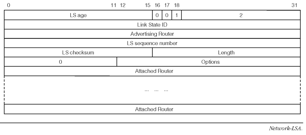
Figure 1-32 shows the format of the Network-LSA.
The Network-LSA is advertised by a DR. All of the routers that are adjacent to the DR are included in the Network-LSA.
Options This field identifies the router capabilities described in Figure 1-27.
Attached Router This field contains the router ID of the router that is adjacent to the DR.
FIGURE 1-32
FIGURE 1-33
Inter-Area-Prefix-LSA
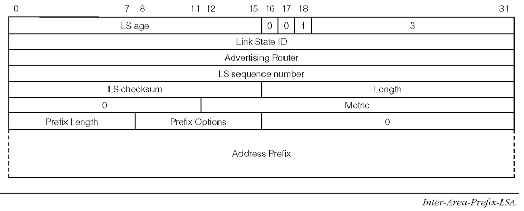
Figure 1-33 shows the format of the Inter-Area-Prefix-LSA.
Metric This field specifies the cost of the advertised route.
Prefix Length This field specifies the significant bits in the Address Prefix field.
Prefix Options This field is shown in Figure 1-28.
Address Prefix This field contains the address prefix. Its size is determined by the Prefix Length rounded to the nearest 32-bit word.
FIGURE 1-34
Inter-Area-Router-LSA
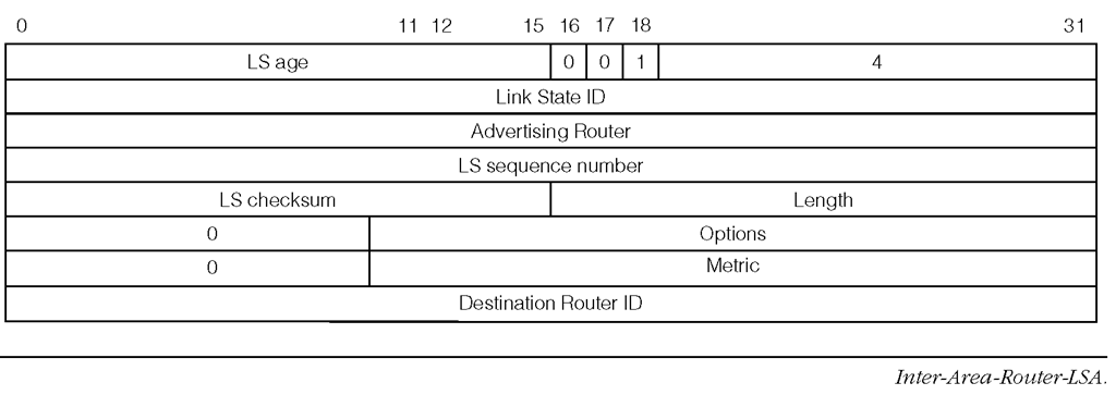
The Inter-Area-Router-LSA is generated by an ABR. Each Inter-Area-Router-LSA describes a single reachable ASBR in the external area.
Figure 1-34 shows the format of the Inter-Area-Router-LSA.
Options This field identifies the router capabilities shown in Figure 1-27.
Metric This field specifies the cost of reaching the advertised router.
Destination Router ID This field specifies the router ID of the reachable router that is being described by the LSA.
AS-External-LSA
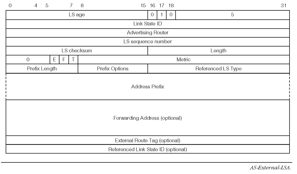
Figure 1-35 shows the format of the AS-External-LSA.
E The E-bit identifies the metric type. If the E-bit is not set, then the metric is a normal metric value having the same unit as the link-state metric. If the E-bit is set, then the metric is considered to be larger than the cost of any intra-AS path, which gives preference to intra-AS paths.
F If the F-bit is set, then the optional Forwarding Address field is set in the LSA.
T If the T-bit is set, then the optional External Route Tag field is set in the LSA.
Prefix Length, Prefix Options, Address Prefix These fields specify the reachable prefix that is imported from outside the AS. These fields have the same meaning as those for the Inter-Area-Prefix-LSA described in Figure 1-33.
Referenced LS Type This field, together with the Referenced Link State ID, and the Advertising Router field helps to associate another LSA that contains additional information about the external route with this LSA. If this field contains a non-zero value then the optional Referenced Link State ID is present in the LSA.
Forwarding Address This field, if present, holds the next hop address for the advertised external route. The unspecified address (::) is invalid for this field.
External Route Tag This field is typically used to help a router in identifying the origin of a route, but its full usage is outside the scope of this topic.
FIGURE 1-35
Referenced Link State ID This field, if present, along with other fields, helps to identify additional information concerning the advertised external route. However, this additional information is not used by OSPFv3.
Link-LSA
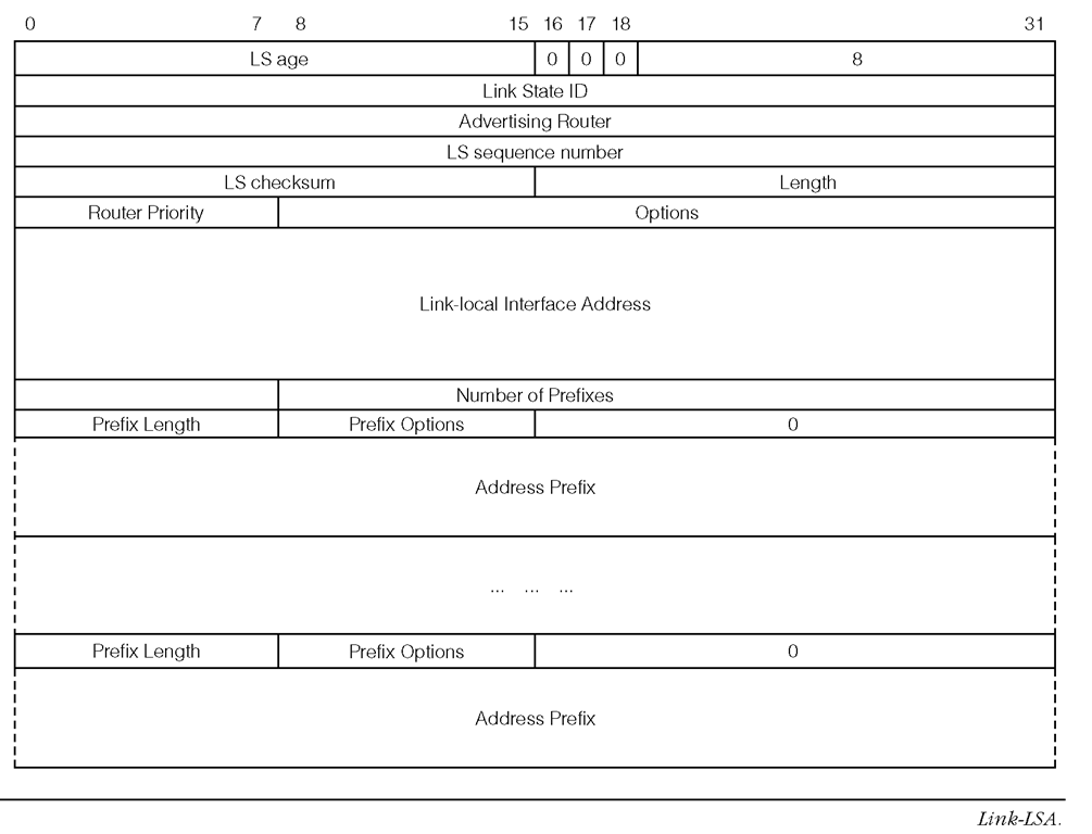
Figure 1-36 shows the format of the Link-LSA.
Router Priority This field specifies the router priority on the interface that is attached to the link being described by this LSA. The router priority is a configured value and it is configurable per interface.
Options This field contains the options that the advertising router would like to set in the Network-LSA to be advertised by the link’s DR.
Link-local Interface Address This field contains the link-local address of the router’s interface that is attached to the link being described by the LSA.
Number of Prefixes This field specifies the number of prefixes that are described by the LSA. Each prefix is described by one set of Prefix Length, Prefix Options and the Address Prefix.
Prefix Length, Prefix Options, Address Prefix These fields specify a prefix that is associated with the link that is being described by the LSA. These fields have the same meaning as those for the Inter-Area-Prefix-LSA described in Figure 1-33.
FIGURE 1-36
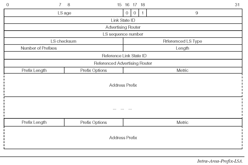
Figure 1-37 shows the format of the Intra-Area-Prefix-LSA.
Intra-Area-Prefix-LSA
Number of Prefixes This field specifies the number of prefixes that are described by the LSA.
Referenced LS Type, Referenced Link State ID, Referenced Advertising Router These fields together identify the LSA (either a Router-LSA or a Network-LSA), which is associated with the advertised prefixes. The advertised prefixes are associated with a Router-LSA if the Referenced LS Type is 0×2001. In this case the Link state ID must be set to 0, and the Referenced Advertising Router field must be set to the router ID of the LSA’s originating router. The advertised prefixes are associated with a Network-LSA if the Referenced LS Type is set to 0×2002. In this case the Referenced Link State ID field is set to the interface ID of the corresponding interface of the DR. The Referenced Advertising Router field is set to the DR’s router ID.
Prefix Length, Prefix Options, Address Prefix These fields specify a prefix that is associated with the router, or one of its attached stub-network segments, or one of its attached transit network segments.
FIGURE 1-37
These fields have the same meaning as those for the Inter-Area-Prefix-LSA described in Figure 1-33.
Metric This field specifies the cost of the advertised prefix. 1.6.5 OSPF Tree Construction and Route Computation
The OSPF LSAs allow each router to build a connected, directed graph that contains all of the reachable networks and nodes within the AS. Each graph node represents a network or a router. Once this graph is built, each router runs the Dijkstra/Prim algorithm to compute a minimum cost route to each possible destination network and node. At the completion of running the Dijkstra algorithm, the graph becomes a tree structure called a shortest path tree because the cost between any pair of tree nodes has the lowest cost out of all alternatives.
The Dijkstra algorithm belongs to a class of algorithms that are known as the greedy algorithm used to solve optimization problems. The greedy aspect comes from the fact that each step picks a local-optimal solution that may eventually lead to a global optimal solution. The reader is encouraged to read references such as [Baa88] for more discussion on the Dijkstra algorithm.
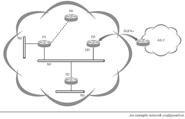
Figure 1-38 illustrates a network configuration that we will use to describe the creation of a shortest path tree from an LSDB. We will consider only the Router-LSA, Link-LSA, Intra-Area-Prefix-LSA, the Network-LSA, and AS-External-LSA to simplify the discussion. In the resulting tree, a reachable router and a network are represented by tree nodes, while the link between routers or the link between a router and a network is represented by an edge.
FIGURE 1-38
These nodes and edges are described by the Router-LSAs, Intra-Area-Prefix-LSA, Link-LSAs and Network-LSAs, which are all maintained in the LSDB. We call a node that is already a part of the shortest path tree a tree node, while a node that is still in the LSDB and remains to be selected as a part of the tree we call a fringe node. The router that runs the Dijkstra algorithm begins by building the tree with itself as the first tree node. Then the algorithm runs an iterative process that:
Step 1. selects a minimum cost link between a tree node and a fringe node among all possible alternatives between this pair of nodes
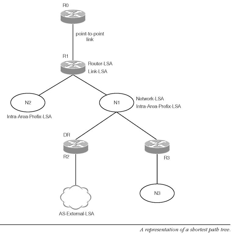
Step 2. repeats the previous step until all fringe nodes have been selected and become tree nodes Figure 1-39 illustrates router R0′s view of the AS at the completion of the Dijkstra algorithm. As can be seen from this figure, once the shortest path tree is obtained, the router has the complete path to each possible destination of the AS, although the routing table contains only the first hop of each path. Also shown in the figure are some of the LSAs that generated the tree nodes.
Router R0 builds the tree by adding itself first into an empty tree. R1′s Router-LSA allows R0 to add R1 into the tree. The link type and the cost of the link are identified by the Link-LSA, which is represented by the edge between the two nodes labeled R0 and R1 in the figure. Inside R1′s Router-LSA, the Neighbor Interface ID and the Neighbor Router ID allow R0 to identify R2′s Network-LSA from the LSDB regarding network N1. Note R2 is the DR for N1 and thus R2 generates the Network-LSA. From this Network-LSA, R0 can subsequently add routers R2 and R3 into the tree. Once R2 is inserted into the tree, R0 can identify and retrieve R2′s AS-External-LSA and adds the referenced prefix (an external network) into the tree. Once R3 is inserted into the tree, R0 can identify R3′s Intra-Area-Prefix-LSA and adds the referenced prefix (a subnetwork N3) into the tree as a reachable node.
Each edge in this graph has a weight or cost associated with it. For example, the cost of the edge between R1 and N2 is the metric value advertised by the Intra-Area-Prefix-LSA. The cost between R1 and network N1 is specified by the metric value of the interface advertised by R1′s Router-LSA.
Figure 1-39 and its description illustrates only a simple example for the purpose of explaining the shortest path tree concept in the context of OSPFv3. In reality, for example, when R0 adds R2 into the tree, it must examine multiple LSAs from the LSDB and consider all of the possibilities of reaching R2.
FIGURE 1-39
R0 then chooses the minimum cost path between itself and R2. This path, which includes nodes (routers and networks) and edges (various links), is inserted along with R2 into the shortest path tree. This minimum cost is the sum of the costs of the edges between R0 and R2.
After completing the shortest path tree, R0 will use the link-local address of R1 as advertised in its Link-LSA as the next hop to reach the networks N1 and N2, the routers R2 and R3, and the external network. R3 will use the link-local address of R2 as advertised in its Link-LSA as the next hop to reach the external network.
