Level 3: Compound Operations
Combining dilation and erosion in different ways results in a number of different image processing tools. These are denoted compound operations. Here we present three of the most common compound operations, namely Opening, Closing, and Boundary Detection.
Fig. 6.8 Erosion with different sized structuring elements
Fig. 6.9 Closing of the binary image in Fig. 6.4 using S1
Closing
Closing deals with the problem associated with dilation, namely that the objects increase in size when we use dilation to fill the holes in objects. This is a problem in situations where, for example, the size of the object (number of pixels) matters. The solution to this problem is luckily straightforward: we simply shrink the object by following the Dilation by an Erosion. This operation is denoted Closing and is written as
where SE is the structuring element. It is essential that the structuring elements applied are exactly the same in terms of size and shape. The closing operation is said to be idempotent, meaning that it can only be applied one time (with the same structuring element). If applied again it has no effect whatsoever except for of course a reduced size of g(x, y) due to the border problem. In Fig. 6.9, closing is illustrated for the binary image in Fig. 6.4. Closing is done with structuring element S1. We can see that the holes and convex structures are filled, hence the object is more compact. Moreover, the object preserves its original size.
In Fig. 6.10 the closing operation is applied to a real image. We can see that most internal holes are filled while the human object preserves its original size. The noisy objects in the background have not been deleted. This can be done either by the operation described just below or by finding and deleting small objects, which will be described in the next topic.
Fig. 6.10 Closing performed using 7 x 7 box-shaped structuring elements
Fig. 6.11 Opening of the binary image in Fig. 6.4 using S1
Opening
Opening deals with the problem associated with erosion, namely that the objects decrease when we use erosion to erase small noisy objects or fractured parts of bigger objects. The decreasing object size is a problem in situations where for example the size of the object (number of pixels) matters. The solution to this problem is luckily straight forward, we simply enlarge the object by following the erosion by a dilation. This operation is denoted Opening and is written as
where SE is the same structuring element. This operation is also idempotent as is the case for the closing operation. In Fig. 6.11 opening is illustrated for the binary image in Fig. 6.4. Opening is done with structuring element Si. We can see that only a compact version of the object remains.
In Fig. 6.12 opening is applied to a real image using a 7 x 7 box-shaped structuring element. We can see that most noisy objects are removed while the object preserves its original size.
Fig. 6.12 Opening performed using a 7 x 7 box-shaped structuring element
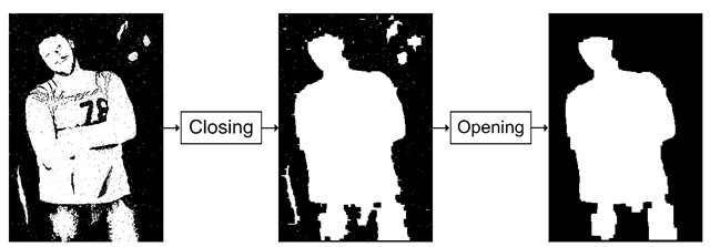
Fig. 6.13 Filtering a binary image where both holes and small noisy objects are present
Combining Opening and Closing
In some situations we need to apply both opening and closing to an image. For example in cases where we both have holes inside the main object and small noisy objects. An example is provided in Fig. 6.13. Note that the structuring elements used in the opening and the closing operations need not be the same. In Fig. 6.13 the closing was performed using a 7 x 7 box-shaped structuring element while the opening was performed using a 15 x 15 box-shaped structuring element.
Boundary Detection
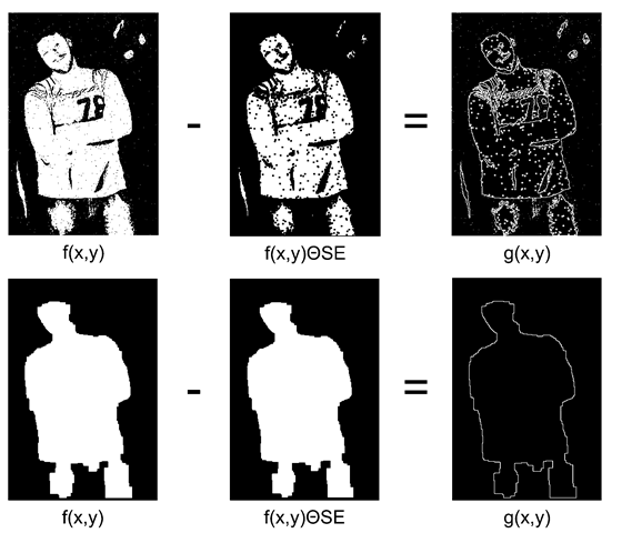
Doing edge detection in binary images is normally referred to as boundary detection and can be performed as described in the previous topic. Morphology offers an alternative approach for binary images. The idea is to use erosion to make a smaller version of the object. By subtracting this from the input image only the difference stands out, namely the boundary:
If the task is only to locate the outer boundary, then the internal holes should first be filled using dilation or closing. In Fig. 6.14 examples of boundary detection are shown.
Fig. 6.14 Boundary detection
Further Information
It has been assumed in this topic that the center of the structuring element is always located on top of the pixel being processed. This need not be the case and the position of the structuring element can be off-set in any direction if need may be. When doing so, please remember to include a procedure in you code that handles the situation when the structuring element or parts hereof is outside the image.
There exit others and more advanced morphologic operations, including gray-level morphology, than those presented in this topic. For inspiration please pick up a topic focusing on these topics, e.g., [7]. In Fig. 6.15 a few examples are provided. The first example illustrates the process of skeletonization, which is closely related to thinning. The latter can produce 1-pixel thin edges as discussed in the previous topic. The other example illustrates the distance transform where the value of a pixel is the distance to the nearest white pixel in the image.


