Surface Modelling with Polygons in Java 3D
The representation of a scene in Java 3D is also based on tesselations of the objects. The elementary geometric objects in Java 3D that were introduced in Sect. 5.4 are approximated by triangles. Figure 6.11 shows the tesselations for the elementary geometric objects in the program StaticSceneExample.java. A representation in the form of a wire frame model as shown in Fig. 6.11 can be achieved in Java 3D by setting the PolygonAttributes of the corresponding
Figure 6.11 was generated with the program TesselationBWExample.java. No colours were used, all objects are drawn with the same black Appearance for which the PolygonAttributes were set as described above. In the program TesselationExample.java the original colours of the scene are kept and PolygonAttributes were only set for the green Appearance so that only the cockpit of the helicopter, its tail and the treetop are shown as wire frames.
The resolution for the tesselation of the elementary geometric objects can also be controlled in Java 3D. The only exception is the box. It has six rectangular faces and each of them can be exactly modelled by two triangles so that there is no need for a higher resolution.
The constructor
generates a sphere with radius r and the Appearance sphereApp whose surface is approximated by res triangles at the circumference. This constructor was used in the program TesselationResolution.java with different values for the resolution res to create Fig. 6.12.
The constructors
generate a cylinder and a cone, respectively, with radius r, height h and Appearance app. For the approximation of the surfaces, xres triangles are used around the circumference and yres triangles along the height. For a nice approximation, the value xres should be chosen larger whereas for yres even the value 2 might be sufficient.
Java 3D offers a variety of ways to model surfaces of geometric objects by approximations with polygons. Here, as one representative of these methods, only approximations with triangles are considered. Usually, the approximation of complex surfaces by triangles will not be specified directly. Instead, suitable software tools are used for this purpose. For measurements of existing objects there are programs that can convert the data into surfaces. CAD programs and other design tools offer a selection of methods like freeform surfaces, CSG and sweep representation together with elementary geometric objects. How to import objects or files created with such tools into Java 3D will be explained in Sect. 6.5.
For modelling surfaces of objects directly with triangles, the class GeometryArray is available. In the first step, the vertices of the triangles must be stored in an array.
The coordinates of the points are given as float-values. For the tetrahedron in Fig. 6.4 on page 131, this array would contain four instances of the class Point3f. This array specifies only the points for vertices, but not which points should form a triangle. An integer array is responsible for this. For each triangle, the indices of the corresponding points in the Point3f array are entered subsequently into this array. For the tetrahedron in Fig. 6.4 the array would have the following entries:
The number of vertices and the number of triangles coincide just by chance for a tetrahedron. For other geometrical shapes this will not be the case. A cube, for example, would require eight vertices and twelve triangles, two for each side of the cube. It is important to specify the points for each triangle in the correct order. The points should be given in anticlockwise order when looking at the surface from the outside.
The following lines of code generate an instance ga of the class GeometryArray from the specified vertices and triangles:
Then this GeometryArray ga can be used to create an instance of the class Shape3D with a predefined Appearance app.
Shape3D myShape = new Shape3D(ga,app);
This Shape3D object can be integrated into a scene in the same way as the elementary geometric objects cube, sphere, cylinder and cone.
A tetrahedron is constructed in this way in the class GeomArrayExample.java. It is interesting to see what happens if the vertices of one of the triangles are specified in the wrong order. One could, for instance, change the order of the points in the first triangle from 0, 1, 3 to 0, 3, 1. The front face of the tetrahedron will obtain the reverse orientation and becomes invisible from the front.
Importing Geometric Objects into Java 3D
Although it is in principle possible to model surfaces of complex geometric objects with triangles, it is an impossible task to specify all triangles explicitly. Various file formats for 3D computer graphics objects can be imported into Java 3D programs. In this way, modelling and design tools can be used to create complex geometric objects which can then be integrated into animated scenes in Java 3D. As an example, importing files in the Wavefront Object format will be explained here in detail. In the topic and on the web site of this topic, there are links to web sites where threedimensional objects in this format can be downloaded as well as links to programs for creating objects in Wavefront Object format.
Files in Wavefront Object format are normal ASCII files containing the following information. Comment lines start with the symbol #. The vertices needed for modelling the three-dimensional object start with the letter v followed by three values determining the x-, y – and z-coordinate of the corresponding vertex. In the same way, normal vectors are specified starting with vn (vertex normals) instead of v. In addition, points for attaching textures can be defined. They are marked by vt (texture vertices). The description of polygons starts with the letter f (face). A polygon is defined by the indices of its vertices. Indices of corresponding normal vectors also belong to polygons. The letter g (group) is used for groupings. In this way, polygons can be combined to a group and can be addressed as subobjects. For example, a helicopter might have groups for the cockpit, the rotor blade and the tail. A name can be assigned to each group. Then Java 3D can directly access such groups and, for instance, assign individual colours to them.
With the following lines of code the file filename.obj in Wavefront Object format can be loaded to a Java 3D scene:
Then this loaded object can be assigned to a transformation group tg, as usual, with the method addChild using the method getSceneGroup.
tg.addChild(s.getSceneGroupO);
The method getNamedObjects provides a Hashtable with the names of all groups that are defined in the loaded file so that subobjects can be accessed. The following lines of code print the names of these subobjects:
If there is, for example, a subobject with the name partName and this subobject should obtain a new colour given by the Appearance app, then this can be achieved by
In this way, it is also possible to use only parts of an object in Wavefront Object format in a scene. After loading the Wavefront Object file, the whole object is not assigned to the transformation group tg as above, but only the subobject with the group name partName is chosen and endowed with the Appearance app by the following lines of code:
The program Load3DExample.java demonstrates how to include an object in Wavefront Object format into a Java 3D program, how to print out all its group names, and how to assign a colour to a specific subobject. The program Extract3DExample.java shows how to extract a single subobject and how to include only this subobject with a desired colour in a scene.
Surfaces as Functions of Two Variables
One way of modelling a surface in 3D space is to define the surface as an implicit function
The surface corresponds to all points (x,y,z) satisfying F(x, y, z) = 0. However, there are various disadvantages that come along with this way of representing a surface. The definition of an implicit function that corresponds to the surface can be extremely difficult. Even if there is a description of the surface as an implicit function, it is necessary to compute the points that satisfy the corresponding equation. Solving such equations often requires numerical methods.
A better alternative for the representation of surfaces is the use of explicit functions
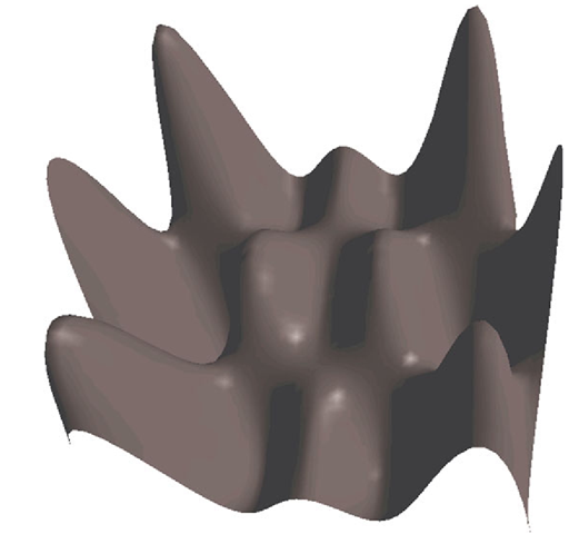
Figure 6.13 shows the function
as an example for such a representation.
It is not possible to model a solid closed shape by a single explicit function. But one can join the surfaces from different functions together to model the surface of a solid body.
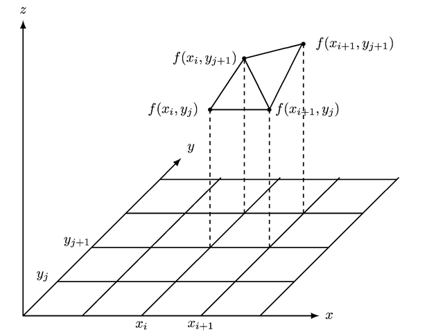
The surface defined by the function (6.1) needs to be approximated by triangles to be displayed in the framework of computer graphics. This can be achieved by considering a rectangular grid on the x/y-plane. For each grid point (xt,yj) the corresponding value of the function zij = f(xi,yj) is calculated.
Fig. 6.13 The surface defined by the function z = x sin(7x) cos(4y)
The points (xi,yj,zij) are then used to determine the triangles to approximate the surface. Two triangles will be defined for each rectangle of the grid in the x/y-plane. For the rectangle determined by the two points (xi,yj) and (xi+i ,yj+i) in the x/y-plane, the corresponding triangles for the surface are
Figure 6.14 illustrates this construction.
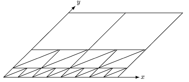
How well the function or the surface is approximated by the triangles depends on the curvature of the surface and the resolution of the grid. A very high resolution of the grid will lead to a better approximation but will also result in a large number of triangles and will therefore be computationally demanding during the rendering process. It is therefore recommended to apply a similar technique like the quadtrees, which were introduced in Sect. 6.3.
If the function is defined over a rectangular area, it will first be approximated by only two triangles that result from splitting the rectangular area into two triangles. If the maximum error of the approximation with these two triangles is small enough, i.e. it does not exceed a certain threshold ε > 0, the rectangle will not be further split into smaller rectangles. As an error measure one can use the absolute error in z-direction, i.e. the absolute difference between the z-value of the function and the z-value of the corresponding point on the surface of the triangle. If the error is too large, the rectangle is further split into four smaller rectangles.
The above construction with the two triangles is then applied to each of the four smaller rectangles. If the error is too large on a smaller rectangle, this rectangle will be further divided into four smaller rectangles. This recursive splitting of rectangles is stopped either when the approximation is good enough or when a maximum number of splitting steps is reached. The latter criterion, limiting the number of steps, guarantees that the splitting will terminate even if the function is discontinuous or has a pole at the boundary of the region on which it is defined.
Fig. 6.14 Approximation of a surface defined by a function using triangles
For arbitrary functions it might not be possible to find the maximum error on a given rectangle in closed form solution. One can use a refined grid and evaluate the function only on the points of this refined grid to estimate the maximum error. The refined grid can be based on the size of the smallest rectangles that would be allowed for the splitting process.
Representation of Landscapes
Nonlinear surfaces will usually not be defined by arbitrary functions z = f(x,y), but will be composed of a number of low degree polynomials or rational functions that enable an intuitive and easy way to model surfaces. This approach of modelling surfaces will be introduced in more detail in Sect. 6.8.
The technique for the representation of surfaces based on functions of the form z = f(x,y) can be applied to model landscapes as they are for instance needed for flight simulation. First of all, artificial landscapes with hills, bumps and other such structures can be generated easily by suitable functions. But also real landscapes can be rendered using the above technique for function approximating based on triangles. Here we only consider the geometry or topology of the landscape and not the precise appearance of the surface like a grassy plane, a tarmac road or a stone desert. This would be a matter of textures that are discussed in Sect. 8.8.
Fig. 6.15 LOD resolution of a landscape with geometry clipmaps
For a real landscape we usually have altitude information available. This altitude information specifies for each point on a sufficiently dense grid how high the point is with respect to some reference level, for instance with respect to the sea level. This means that the topology of a landscape might be given in a file in which for each grid point the corresponding altitude is specified. Instead of evaluating the function z = f(x,y) at the corresponding grid points (xt,yj), we can replace the value zij = f(x\ ,yj) by the altitude Hij of the corresponding point in the landscape to be modelled.
Using the finest available grid for a larger landscape would lead to a very large number of triangles. On the one hand, a high resolution of the landscape is definitely not necessary for parts of the landscape that lie in the far distance. On the other hand, for the close parts of the landscape a higher resolution is needed to generate realistic images. Therefore, instead of using a fixed resolution, the resolution is dynamically adapted, depending on how far away the corresponding part of the landscape is from the viewer. The closer the corresponding part of the landscape, the higher its resolution is chosen. The farther away the landscape, the larger the triangles that are used for modelling (compare [1, Chap. 2]). Figure 6.15 illustrates this principle of geometry clipmaps. The altitude information is not displayed in the figure, only the resolution of the grid and the triangles.
Rendering techniques where the number of triangles for displaying a surface depends on the distance of the viewer to the surface are not only applied in the context of landscapes, but also for other objects and surfaces that are approximated by a larger number of triangles. When the viewer is very close to the object, a high resolution with a large number of triangles is used for rendering the object. If the object is in the far distance, a very coarse resolution with only a few triangles is used. This technique is called LOD (level of detail). The implementation of the LOD technique in Java 3D is explained in Sect. 9.11.
The methods described in this section refer only to geometric or topological modelling of landscapes. Once the geometry is generated, it is still necessary to add textures to model different surfaces like grass, sand or tarmac. The application of textures to surfaces in 3D is explained in Sect. 8.8.
![tmpc009-292_thumb[2] tmpc009-292_thumb[2]](http://what-when-how.com/wp-content/uploads/2012/06/tmpc009292_thumb2_thumb.png)
![tmpc009-294_thumb[2] tmpc009-294_thumb[2]](http://what-when-how.com/wp-content/uploads/2012/06/tmpc009294_thumb2_thumb.png)
![tmpc009-295_thumb[2] tmpc009-295_thumb[2]](http://what-when-how.com/wp-content/uploads/2012/06/tmpc009295_thumb2_thumb.png)
![tmpc009-296_thumb[2] tmpc009-296_thumb[2]](http://what-when-how.com/wp-content/uploads/2012/06/tmpc009296_thumb2_thumb.png)
![tmpc009-297_thumb[2] tmpc009-297_thumb[2]](http://what-when-how.com/wp-content/uploads/2012/06/tmpc009297_thumb2_thumb.png)
![tmpc009-298_thumb[2] tmpc009-298_thumb[2]](http://what-when-how.com/wp-content/uploads/2012/06/tmpc009298_thumb2_thumb.png)
![tmpc009-299_thumb[2] tmpc009-299_thumb[2]](http://what-when-how.com/wp-content/uploads/2012/06/tmpc009299_thumb2_thumb.png)
![tmpc009-300_thumb[2] tmpc009-300_thumb[2]](http://what-when-how.com/wp-content/uploads/2012/06/tmpc009300_thumb2_thumb.png)
![tmpc009-301_thumb[2] tmpc009-301_thumb[2]](http://what-when-how.com/wp-content/uploads/2012/06/tmpc009301_thumb2_thumb.png)
![tmpc009-302_thumb[2] tmpc009-302_thumb[2]](http://what-when-how.com/wp-content/uploads/2012/06/tmpc009302_thumb2_thumb.png)
![tmpc009-303_thumb[2] tmpc009-303_thumb[2]](http://what-when-how.com/wp-content/uploads/2012/06/tmpc009303_thumb2_thumb.png)
![tmpc009-304_thumb[2] tmpc009-304_thumb[2]](http://what-when-how.com/wp-content/uploads/2012/06/tmpc009304_thumb2_thumb.png)


