In the previous topic, objects of the virtual world were constructed with elementary geometric shapes like boxes, spheres, cylinders and cones. These simple shapes are not sufficient to model surfaces of more complex objects. This topic introduces a variety of techniques for modelling three-dimensional objects and their surfaces.
Three-Dimensional Objects and Their Surfaces
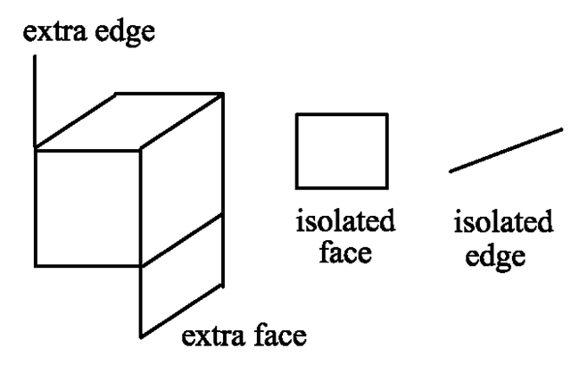
Before discussing methods for modelling three-dimensional objects, it should be clarified what kinds of object are considered in computer graphics. In principle, any subset of the space R3 could be seen as a three-dimensional object. However, this would mean that even single points, edges or planes are considered to be threedimensional. One could view a piece of paper as a two-dimensional plane. But even the thinnest paper has a nonzero thickness and is therefore an extremely flat box. Figure 6.1 shows some examples of how three-dimensional objects should not look like. Isolated or dangling edges and faces as seen in the figure should be avoided.
For the purpose of showing a three-dimensional object, its surface is of importance, not the set of points in the three-dimensional space that are occupied by the object. Transparent objects can be considered as an exception. Therefore, the intention of computer graphics techniques for modelling objects usually focusses on surfaces and not on sets of points in R3. In certain applications, for instance when objects are measured with 3D scanners or in the case of tomography data, no explicit definition of the surface of the object is available. In such cases it is very common that the object is first described as a three-dimensional set of points and then the object’s surface is derived from this set.
There are various sophisticated techniques for modelling complex surfaces with round and bent shapes. However, these models are usually not taken directly for the generation of an image of a scene. Instead, surfaces are approximated by a larger number of polygons, triangles in most cases, in order to simplify computations for illumination and projection. For arbitrary surfaces it might even be impossible to find an analytical expression for the representation of the projection.
Fig. 6.1 Isolated and dangling edges and faces
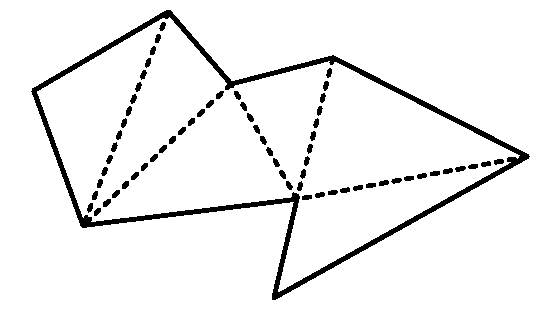
Fig. 6.2 Triangulation of a polygon
Efficient and fast calculations of projections would become impossible. The situation is much easier for polygons. The intersection point of a plane polygon with a line representing a projector is simple and fast. The approximation of a curved surface by polygons is called tesselation. Using only triangles for the polygons is no real restriction since any polygon can be partitioned into triangles. Figure 6.2 shows a triangulation of a polygon. The dashed lines split the polygon into triangles. Triangles have the advantage that very efficient computer graphics algorithms are available for them, which can also be directly implemented on a graphics card. Another disadvantage of polygons with more than three edges is that it must be ensured that all vertices lie in the same plane.
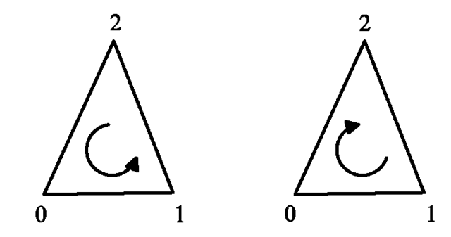
The single triangles or polygons for modelling a surface are usually oriented in order to determine which side of the polygon is on the outside of the surface. The orientation is given by the order of the polygon’s vertices. The vertices are listed in anticlockwise order when looking onto the surface from the outside of the object.
In Fig. 6.3 this means that the triangle with the vertices 0, 1, 2 is oriented in the direction of the viewer. The viewer can see the front of this part of the surface. The same triangle, but with orientation 0, 2, 1 of the vertices would remain invisible for the viewer since he can only see this part of the surface from the back. The surface would be invisible since it is impossible to see the surface of a solid threedimensional object from the inside. When polygons have an orientation, rendering can be accelerated significantly since surfaces that do not point to the viewer can be ignored for the whole rendering process.
Isolated and dangling faces should be avoided since they can lead to unrealistic effects. They can be seen from one side, but become invisible from the other.
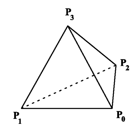
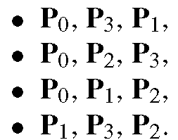
Figure 6.4 shows a tetrahedron with vertices P0, P1, P2, P3. The four faces in the form of triangles of the tetrahedron can be defined by the following groups of vertices:
Fig. 6.3 Orientation of polygons
Fig. 6.4 A tetrahedron
For the specification of the triangles, the vertices of each triangle are listed in an anticlockwise manner when looking at the corresponding triangle from the outside of the tetrahedron.
Topological Notions
This section introduces elementary concepts from topology to better understand the problems of modelling three-dimensional objects and their surfaces. The definitions are given for the general case Rp. Here they are only needed for the cases p = 3 and p = 2. The latter case is used for illustration purposes. Areas are the two-dimensional counterparts of three-dimensional objects.
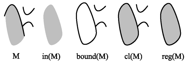
In the left-hand side, Fig. 6.5 shows a set M of points in the plane with isolated and dangling edges. Based on the topological notions which are introduced in the following, this set of points can be regularised, resulting in the area on the right-hand side of the figure without isolated or dangling edges.
In order to explain the topological notions, a set M c Rp is considered in the following. A subset U c Rp is called a neighbourhood of the point x0 e Rp if there exists ε > 0 such that
Fig. 6.5 A set M c R2 of points, its interior, boundary, closure and regularisation
In the two- and the three-dimensional case, this means that a neighbourhood of a point must contain at least a small circle or sphere, respectively, around the point. A point x e M is called an inner point of M if there is a neighbourhood U of x such that U ç M holds. In the two- and the three-dimensional case, this means that there must be at least a small circle or sphere around a point x, completely contained in M, to be an inner point of M.
The set
of all inner points of M is called the interior or kernel of M. The interior of M is shown directly next to the set M in Fig. 6.5.
A point x is called a boundary point of M if every neighbourhood of x has nonempty intersections with M as well as with the complement of M. The set
of all boundary points of M is called the boundary of M, which is illustrated in the middle of Fig. 6.5. The interior of a set can also be defined as the set without its boundary.
M is called an open set if M coincides with its interior, i.e., if in(M) = M holds. The union of a set M with its boundary
is the closure of M, which is shown as the second set from the right in Fig. 6.5.
M is called closed if the closure of M is M itself, i.e., if cl(M) = M holds. The regularisation of M is the closure of the interior of M.
The regularisation of a set will cut off isolated as well as dangling edges and faces as can be seen on the right-hand side of Fig. 6.5.
The set M is called regular if reg(M) = M holds, i.e., if the set coincides with its regularisation.
In addition to the regularisation of three-dimensional objects, it might also be necessary to remove inner surfaces. The inner surfaces of a hollow object will never be needed for rendering so that it is better to remove them completely for efficiency reasons.
Modelling Techniques
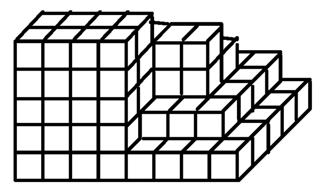
Voxels are a very simple technique for modelling three-dimensional objects. The three-dimensional space is partitioned into a grid of small, equisized cubes, called voxels. Voxels are the three-dimensional counterpart of a pixel grid. A threedimensional object is defined by those voxels that lie within the interior of the object. Voxels are suitable for modelling objects based on tomography data, which provide information about the tissue density inside the measured body or object. For instance, if the bones of a body should be represented, those voxels would be considered where a density corresponding to bones has been measured.
Figure 6.6 illustrates the representation of a three-dimensional object based on voxels.
The computational costs in terms of memory and time for handling voxel models can be enormous. Seeing the voxel grid as the three-dimensional counterpart of a two-dimensional pixel grid and using similar resolution, this would mean that instead of 1000 x 1000 pixels, 1000 x 1000 x 1000 = 109 voxels are needed. It is out of discussion that such models can be used for immediate image generation.
Octrees are an efficient alternative to voxel models. They are based on voxels with varying size. Only in those parts where a fine resolution is needed, small voxels are used. For instance, when a sphere-like object should be modelled by voxels, there is no need to fill the sphere with a large number of small voxels. It is sufficient to fit one big voxel into the sphere and use smaller voxels only for the representation of the surface. For an octree, the object to be modelled is first fit into a sufficiently large cube or a box. Then this cube is split into eight smaller cubes. Smaller cubes that lie completely inside or completely outside the object are marked with in and off, respectively. For these cubes, there is no need for further refinement. The other cubes are marked with on, indicating that the cube intersects the surface of the object. All cubes marked with on are further subdivided into smaller cubes and the smaller cubes are marked and processed in the same way until the maximum desired resolution, i.e., the minimum allowed cube size, is reached.
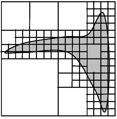
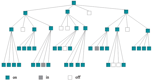
For illustration purposes, the two-dimensional counterpart of octrees is considered here. They are based on the same principle, partitioning an area into squares or rectangles of varying size. Since larger squares are divided into four smaller squares, they are called quadtrees. Figure 6.7 shows an area surrounded by a square which is recursively partitioned into smaller squares. Smaller squares are only divided further if they intersect the boundary of the area. The process is stopped when the squares have reached a predefined minimum size. The corresponding quadtree is shown in Fig. 6.8. Octrees are similar to quadtrees, but their inner nodes have eight instead of four child nodes since cubes are divided into eight subcubes.
Fig. 6.6 Modelling a three-dimensional object with voxels
Fig. 6.7 Recursive partition of an area into squares
Voxel models and octrees are tailored for representing objects based on data obtained using specific 3D measurement techniques. For efficiency purposes, a raw voxel model can be turned into an octree easily. Nevertheless, both models are not suitable for realistic representations of object surfaces. For proper illumination and light reflection effects, it is very important to take the slope of the surface into account. The cubes in voxel models and octrees have no tilted surfaces. Their surfaces always point in the direction of the coordinate axis. Therefore, for objects that are modelled by voxels or octrees, the surfaces should be approximated by parametric freeform surfaces, which will be introduced in Sect. 6.8.
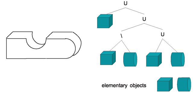
When real objects are measured and the data should be used directly for generating 3D models, then voxels and octrees might be a good approach. But there are better suited techniques for modelling virtual objects that are usually integrated into specific object modelling and CAD tools. It would be too tedious to describe virtual curved objects by specifying an enormous amount of tiny voxels. One technique better suited for direct modelling is the CSG scheme where CSG stands for constructive solid geometry. The CSG scheme is based on a collection of elementary geometric objects. Transformations and regularised set-theoretic operations can be applied to these objects to construct more complex objects. Set-theoretic operations like union, intersection and difference were introduced in Sect. 2.3 in the context of two-dimensional objects. The same principles apply to three-dimensional objects. Regularisation is carried out in addition to avoid isolated and dangling edges and faces. Figure 6.9 shows an object on the left which was constructed from the elementary objects box and cylinder. The right part of the figure speci- fies how the corresponding elementary objects were combined with set-theoretic operations to obtain the object on the left. The necessary transformations are not included in the figure. For instance, the centre part of the shown object is generated from a box from which a cylinder was subtracted, resulting in the half-circle-shaped bulge.
Fig. 6.8 The quadtree for Fig. 6.7
Fig. 6.9 An object that was constructed using elementary geometric objects and set-theoretic operations shown on the right
Another useful solid modelling technique is the sweep representation. A threedimensional object is generated from a two-dimensional shape that is moved along a trajectory. For instance, the horseshoe-shaped object on the left in Fig. 6.10 is created from a rectangle which is moved along an arc. The tent shape on the right-hand side of the figure originates from a triangle sliding along a line.
Fig. 6.10 Two objects and their sweep representations
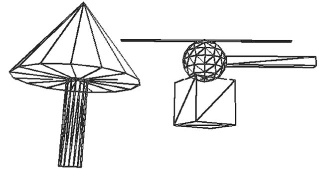
Fig. 6.11 Tesselation of the helicopter scene in Fig. 5.3
The probably most important modelling technique, which will be introduced in Sect. 6.8, is based on freeform surfaces that are defined by parametric curves. As mentioned before, curved surfaces will be approximated by plane polygons for the generation of images. The description of the surface of an object by polygons requires a list of points—the vertices of the polygons—and a list of polygons composed of these points. Apart from this geometrical structure, information about the colour or texture of the surface as well as normal vectors assigned to the polygons or vertices is needed for calculating the correct illumination and shading caused by light reflections. So when a curved surface is approximated by polygons, not only the vertices and faces of the polygons are stored, but also normal vectors of the original surface in the vertices of the polygons.
Also the surfaces of the elementary geometric objects in the simple scene with the helicopter in Fig. 5.3 on page 107 are approximated by triangles. Figure 6.11 shows the underlying tesselation.
The larger the number of triangles, the better the curved surface can be approximated. Figure 6.12 shows a sphere for which the tesselation was refined from left to right. The left sphere is approximated by only eight triangles. The computational effort increases with the number of triangles. The approximation of a surface by triangles can be carried out off-line before the rendering process. But also the calculations for light reflections on the surface, the determination of which objects or polygons are hidden from view by others as well as collision detection, i.e., whether moving objects collide, become more complex with an increasing number of triangles. Usually, a higher resolution will lead to a quadratic increase of the computational costs because, for example, doubling the resolution in each dimension for a two-dimensional surface approximation requires four times as many triangles.
Fig. 6.12 Representation of a sphere with different tesselations
For this reason, the same object might be stored in different resolutions in a virtual world. For instance, there is no need to have a detailed model of each tree when a forest is viewed from the distance. A very rough approximation with few triangles is sufficient for each tree. For an extremely refined resolution, each triangle might not even cover a single pixel in the projection when the tree is viewed from the distance. So the computational effort can be reduced drastically when simplified tesselations of the trees are used in this case. However, once the viewer approaches the forest, more refined tesselations are required for a realistic image. The viewer might even stand in front of a tree and look at the structure of single leaves. This requires a very high resolution with triangles. This technique of storing an object with different tesselations and deciding which resolution should be used depending on the distance of the viewer to the object is called level of detail (LOD).
