Reflection
In order to achieve illumination and shading effects as in Fig. 8.1 on page 178, it necessary to specify for all surfaces of objects in the scene how they reflect light. The illumination model that is constructed here is not correct from the physical point of view. Ambient light as it is modelled in scenes so far does not exist in reality per se, nor is it constant everywhere. Ambient light is a simplification of real illumination for the purpose of computational simplicity and efficiency. For the same reasons, the light which is reflected by objects is not taken into account for further illumination calculations.Introduction to Computer Graphics Using Java 2D and 3D Objects in a virtual scene only reflect light from defined light sources. They do not reflect the light which is shed on them by reflections of other objects. Ambient light replaces these complex reflections. Section 8.10 will introduce a far more complex model where the light reflections between objects are explicitly calculated.
This section explains light reflection on a surface in detail. A point on a surface of an object is considered and for this point the colour is computed which should be assigned to it taking all light sources in the scene into account as well as the reflection properties of the surface. The single effects introduced in the following usually occur in combination. For each effect, an RGB-value is determined, modelling the reflection of the surface in the corresponding point when only this effect is considered. In order to determine the final colour of the point on the surface, all these effects have to be added. It should be taken into account that the overall intensity for each of the three primary colours red, green and blue is limited by one.
Objects might emit light themselves. It should be emphasised again that the emitted light is only taken into account for this object so that it will occur brighter for the viewer. The emitted light will not illuminate other objects in this simple model. If an object emits light, then this emission contributes a corresponding intensity to each of the primary colours red, green and blue. By this light emitting effect alone, a pixel on the surface of the object i will obtain an intensity of
This intensity must be specified separately for red, green and blue. The object might not emit white light and have therefore different intensities for the three primary colours. The correct specification would be
Since the structure of the illumination equation for all effects will always be the same for the three primary colours, for each effect only one equation for the computation of the intensity will be provided. The corresponding computations have to be carried for the three primary colours and might also lead to different intensities as in the above case when the object does not emit white light, but light of a different colour.
An object emitting light is not considered as a light source in the scene. It only shines for the viewer. Objects emitting light should be combined with a corresponding light source. A light bulb would be modelled by a point light source and a geometric object emitting light. The point light source illuminates the scene, but remains invisible itself. The object does not illuminate other objects, but it shines for the viewer and makes the point light source visible. The intensity on the surface generated by emitting light is constant and does not lead to any 3D effects. When there are no light sources in the scene and only objects emitting light, this will result in the same homogeneous flat projections as in Fig. 8.1 on page 178 for the leftmost object and the second object from the right.
All following illumination effects result from reflections of light coming from light sources in the scene. The illumination equation is always of the form
I light source is the intensity of the light coming from the light source. fpixel is a factor that depends on various parameters. For instance, the colour of the surface, its shininess, the distance to the light source in case attenuation must be taken into account, and the angle at which the light hits the surface in the considered pixel.
For ambient light, the illumination equation is
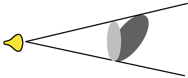
where Is is the intensity of ambient light. ka is the reflection coefficient of the surface for ambient light. In the same way as for objects emitting light, ambient light alone will not lead to any 3D effects. The projections of objects occur flat and have a homogeneous colour. 3D effects result only from light to which a direction can be assigned, in contrast to ambient light coming from all directions or no specific direction. Only if light has a direction, can a non-homogeneous shading occur on an object’s surface. On dull surfaces, a light ray is reflected into all directions equally. How much light is reflected depends on the intensity of the light, the reflection coefficient of the surface and the angle at which the light hits the surface. Figure 8.5 illustrates the influence of the angle at which the light hits the surface. The same energy of light, i.e., the full energy of the light source, reaches the circle, no matter whether it stands perpendicular to the axis of the cone of light or whether it is tilted. But the tilted area is larger than the perpendicular one. This means that the tilted area receives less light per point or pixel than the perpendicular one. The more the area is tilted, the less energy of light will be available per point.
Fig. 8.5 Light intensity depending on the angle of the light
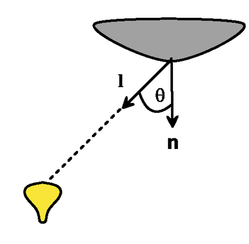
Fig. 8.6 Diffuse reflection
This effect is also responsible for the fact that it is warmer at the equator, where the sun’s rays hit the surface of the earth perpendicular, at least in spring and autumn, and colder at the north and south pole. The seasons also result from this effect since the axis of the earth is tilted differently to the sun over the year. During the time between March and September the northern hemisphere is tilted to the sun, during the other half of the year the southern hemisphere is tilted to the sun.
This effect of light reflection for purely dull surfaces can be computed according to Lambert’s cosine law by the illumination equation:
where Il is the intensity of the light hitting the surface, 0 < kd < 1 is the reflection coefficient of the surface or the material, and θ is the angle between the normal vector n to the surface in the considered point and the vector l pointing in the direction where the light comes from. Figure 8.6 illustrates this situation. This kind of reflection on dull surfaces is called diffuse reflection.
The illumination equation (8.3) for diffuse reflection is only valid for angles θ between 0° and 90°. Otherwise, the light ray hits the surface from the backside so that no reflection occurs. In the case of directional light coming from a light source in infinite distance, the variable Il in (8.3) has the same value everywhere. In the case of a point light source, Il is the intensity of the light source multiplied by the attenuation factor in (8.1), which depends on the distance of the point on the surface to the light source. For a spot light in addition to attenuation, the factor in (8.2) modelling how much the spotlight is focussed must be taken into account.
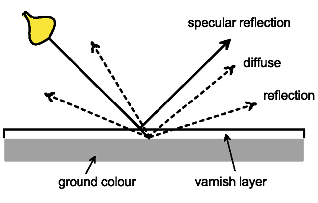
Fig. 8.7 Diffuse and specular reflection
In principle, the illumination equations have to be evaluated for each pixel. Section 8.5 will introduce approximation techniques by which the illumination equations are only evaluated explicitly for certain pixels, usually the vertices of the surface polygons, and for the remaining pixels the value resulting from their illumination equation is estimated by simpler interpolation schemes. Nevertheless, even if the illumination equations are only computed for the vertices of the surface polygons in the scene, this might still be a large number. Therefore, the computationally expensive cosine in (8.3) is computed based on the dot product of the normal vector n to the surface and the vector l pointing in the direction where the light comes from. Both vectors must be normalised for this purpose. The same principle has already been applied in the context of (8.2) on page 180. In this way, (8.3) becomes
In the case of a directional light source and a plane surface, the vectors l and n remain constant on the surface. Then the surface will be shaded homogeneously with the same colour. One can see this effect in Fig. 8.1 on page 178 for the cube on the right which was illuminated by directional light. The faces of the cube are shaded differently since the light hits them in different angles. But the shading on a single face is constant.
Diffuse reflection on dull surfaces reflects the light into all directions. Specular reflection occurs on shiny surfaces. Such shiny surfaces reflect at least a portion of the light in a similar way as a mirror. In contrast to diffuse reflection, ideal specular reflection takes place only in one direction. The vector pointing to the source of light is mirrored about the normal vector of the surface. The vector in the direction of the light and the vector pointing in the direction of the reflection have the same angle with the normal vector to the surface. The difference between diffuse and specular reflection is illustrated in Fig. 8.7.
Shiny surfaces very often have a very thin transparent layer, for instance varnish. When light hits the surface, part of the light penetrates the varnish layer and is reflected on the dull surface of the object. This part of the light is subject to diffuse reflection and the colour of the reflected light depends strongly on the ground colour of the dull surface. Another part of the light is directly reflected on the transparent layer by specular reflection.
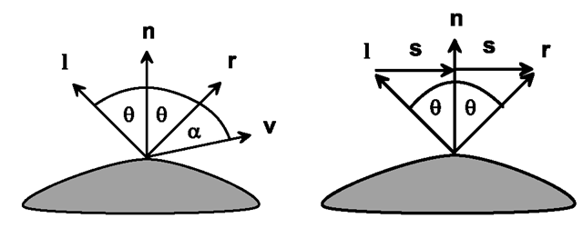
Fig. 8.8 Computation of ideal specular reflection
Therefore, specular reflection does usually not change the colour of the light. This effect can also be seen in Fig. 8.1 on page 178. The second object from the left has a shiny white spot on its surface although the colour of the object itself is grey. This white spot is due to specular reflection. Shading caused by diffuse reflection depends only on the angle at which the light hits the surface and on the reflection coefficient. The position of the viewer is of no importance for calculating effects coming from diffuse reflection. Whether or where the viewer can see specular reflection depends on his position. In the case of a plane surface which is illuminated by a single light source, there will be exactly one point on the surface where the viewer can see ideal specular reflection. This is, however, only true for perfect mirrors. For surfaces that are more or less shiny, the light vector is reflected roughly in the direction around the ideal specular reflection. In this way a circular brighter area occurs on the surface instead of only a single light point in which ideal specular reflection takes place. Before models for nonideal specular reflection can be introduced, it is necessary to find a computation scheme for the direction of ideal specular reflection.
In Fig. 8.8, l denotes the vector pointing in the direction from which the light hits the surface in the considered point. n is the normal vector to the surface in this point. The vector v points in the direction of the viewer, i.e., in the direction of projection. r denotes the direction of ideal specular reflection. The normal vector n has the same angle with the vectors l and r.
In order to compute the direction r of ideal specular reflection for normalised vectors n and l, the auxiliary vector s is introduced, as can be seen in Fig. 8.8 on the right. The projection of l to n corresponds to the shortened vector n, denoted by s in the figure. Since n and l are assumed to be normalised, this projection vector is s = n · cos θ. The vector r must therefore satisfy
The auxiliary vector s can be determined from l and the projection of l onto n.
Inserting s into (8.4) yields
As already in the case of diffuse reflection, the dot product can be used to calculate the angle between the vectors n and l: nT · l = cos θ. Therefore, the normalised vector in the direction of ideal specular reflection is
It is again assumed that the surface is not illuminated from the backside. This means 0° < θ < 90° must hold. This is true if and only if the dot product nT · l is positive.
Only for an ideal mirror, specular reflection will take place exclusively in the direction of the vector r. For most shiny surfaces, specular reflection can be seen around the ideal direction. The more the viewer deviates from the direction of ideal specular reflection, the smaller the effect of nonideal specular reflection will be. The Phong illumination model [7] takes this into account by reducing the intensity of specular reflection based on the angle α in Fig. 8.8. The intensity of specular reflection decreases whilst α increases.
Il is the intensity of the light which might have been reduced already by an attenuation factor for a point light source and by an additional factor for a spotlight, depending on the deviation from the axis of the cone of light. The value 0 < Ψ(θ ) < 1isthe fraction of the light which is directly reflected at the shiny surface, i.e., the fraction of the light to which specular reflection applies. In most cases, Ψ(θ) = ksr will be a constant specular reflection coefficient of the surface independent of the angle θ. n is the specular reflection exponent of the surface. For a perfect mirror, n = œ would hold. A smaller n leads to a less focussed specular reflection. Figure 8.4 on page 181 shows the cosine function with different exponents n. For n = 64, the function tends to zero very quickly so that specular reflection can be seen only very close to the ideal direction of specular reflection. Choosing n = 1 would result in a much larger area of visible specular reflection. The more shiny a surface is, the higher the value of the specular reflection exponent should be chosen.
The value of the cosine function in (8.5) can again be computed by the dot product when the vectors n and r are normalised cos α = rT · v. The vector r will be normalised already when the vectors l and n are normalised. This follows directly from Fig. 8.8.
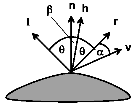
The Phong illumination model is not based on principles of physics. It is a heuristic method to enhance realistic effects of specular reflection. A modified version of the Phong illumination model replaces the deviation of the view direction from the direction of ideal specular reflection, the angle α, by another angle based on the halfway vector between the direction of the light source and the viewer direction. The viewer can see ideal specular reflection when the halfway vector between l and v coincides with the normal vector n to the surface. A reasonable measure for the deviation from the direction of specular reflection is therefore the angle β between the normal vector n and the halfway vector h of l and v, as is shown in Fig. 8.9.
Fig. 8.9 The halfway vector h in Phong’s model
In the modified Phong illumination model, the term cos a in (8.5) is replaced by the term cos β, which can again be written as a dot product.
The halfway vector h is given by
In case of directional light and parallel projection, the halfway vector h does not change, in contrast to the vector r in the original Phong illumination model so that the calculations for illumination can be reduced in the modified Phong illumination model.
The considerations in this section always referred to one light source, a single point on a surface and three primary colours red, green and blue. When there is more than one light source and also ambient light /ambient_light in the scene, the single computed intensities have to be summed up. In case the corresponding surface is also emitting light itself, this intensity /self_emission must also be added. This leads to the following overall illumination equation for the point on the surface:
ka is the reflection coefficient for ambient light which is usually identical to the reflection coefficient kd for diffuse reflection. Ij is the intensity of the jth light source. For a directional light source, the two factors /att and ^cone are equal to one. Only for a point light source, the first factor, modelling attenuation, depends on the distance and for a spotlight the second factor takes into account how fast the intensity of the light decreases to the boundary of the cone of light. n, l, v and r are the vectors known from Figs. 8.8 and 8.6, respectively. Equation (8.6) is based on the original Phong illumination model for specular reflection. The reflection coefficient ksr for specular reflection is usually not identical to the coefficients kd and ka.
The intensity I in (8.6) is bounded by one. If the sum exceeds one, then the intensity is simply cut off at one.
The application of (8.6) for the three colours red, green and blue does not require much additional computational costs since the coefficients Iself_emission, Iambient_light, Ij, ka, kd and ksr might be different for each colour, but are given and do not have to be computed by an algorithm. The other coefficients need more complex calculations. They are the same for every colour, but depend on the chosen point on the surface and the properties of the light source.
Deferred Shading [8] is a recent technique to speed up the calculations when there are multiple light sources in the scene. It is based on the z-buffer algorithm. The original z-buffer might carry out all these complex computations for the projection of a surface only to find out at a later stage that all efforts were superfluous since the surface is not visible and another surface overwrites the projection. In the worst case, unnecessary computations for illumination are carried out again and again until finally the surface or object closest to the viewer is rendered. Deferred Shading first applies the z-buffer algorithm only to fill the depthbuffer with the corresponding z-values of the visible objects and ignores the frame buffer. In the second pass of the algorithm the frame buffer is also filled. But since the z-values are already entered, only those objects need to be projected to the frame buffer that are really visible.
![tmpc009-432_thumb[2] tmpc009-432_thumb[2]](http://what-when-how.com/wp-content/uploads/2012/06/tmpc009432_thumb2_thumb.png)
![tmpc009-433_thumb[2] tmpc009-433_thumb[2]](http://what-when-how.com/wp-content/uploads/2012/06/tmpc009433_thumb2_thumb.png)
![tmpc009-434_thumb[2] tmpc009-434_thumb[2]](http://what-when-how.com/wp-content/uploads/2012/06/tmpc009434_thumb2_thumb.png)
![tmpc009-435_thumb[2] tmpc009-435_thumb[2]](http://what-when-how.com/wp-content/uploads/2012/06/tmpc009435_thumb2_thumb.png)
![tmpc009-438_thumb[2] tmpc009-438_thumb[2]](http://what-when-how.com/wp-content/uploads/2012/06/tmpc009438_thumb2_thumb.png)
![tmpc009-440_thumb[2] tmpc009-440_thumb[2]](http://what-when-how.com/wp-content/uploads/2012/06/tmpc009440_thumb2_thumb.png)
![tmpc009-443_thumb[2] tmpc009-443_thumb[2]](http://what-when-how.com/wp-content/uploads/2012/06/tmpc009443_thumb2_thumb.png)
![tmpc009-444_thumb[2] tmpc009-444_thumb[2]](http://what-when-how.com/wp-content/uploads/2012/06/tmpc009444_thumb2_thumb.png)
![tmpc009-445_thumb[2] tmpc009-445_thumb[2]](http://what-when-how.com/wp-content/uploads/2012/06/tmpc009445_thumb2_thumb.png)
![tmpc009-449_thumb[2] tmpc009-449_thumb[2]](http://what-when-how.com/wp-content/uploads/2012/06/tmpc009449_thumb2_thumb.png)
![tmpc009-450_thumb[2] tmpc009-450_thumb[2]](http://what-when-how.com/wp-content/uploads/2012/06/tmpc009450_thumb2_thumb.png)
