Basic Geometric Objects
The basic geometric objects in computer graphics are usually called primitives or graphics output primitives. They include geometric entities like points, straight and curved lines and areas as well as character strings. The basic primitives are the following ones.
Points that are uniquely defined by their x – and y-coordinate. Points are usually not drawn themselves. Their main function is the description of other objects like lines that can be defined by their two endpoints.
Lines, polylines or curves can be defined by two or more points. Whereas for a line two points are needed, curves require additional control points. Polylines are connected sequences of lines.
Areas are usually bounded by closed polylines or polygons. Areas can be filled with a colour or a texture.
The simplest curve is a line segment or simply a line. A sequence of lines where the following line starts where the previous one ends is called a polyline. If the last line segment of a polyline ends where the first line segment started, the polyline is called a polygon. For various applications—for instance for modelling surfaces— additional properties of polygons are required. One of such properties is that the polygon should not overlap with itself. Convexity is another important property that is often needed. A polygon or, more generally, an area or a region is convex if whenever two points are within the region the connecting line between these two points lies completely inside the region as well. Figure 2.6 shows a self-overlapping polygon, a nonconvex polygon and a convex polygon. For the nonconvex polygon two points inside the polygon are chosen and connected by a dotted line that does not lie completely inside the polygon.
In addition to lines and piecewise linear polylines, curves are also common in computer graphics. In most cases, curves are defined as parametric polynomials that can also be attached to each other like lines in a polyline. The precise definition and computation of these curves will be postponed until Chap. 6. Here it is sufficient to understand the principle of how the parameters of a curve influence its shape. In addition to the endpoints of the curve, one or more control points have to be specified. Usually, two control points are used leading to a cubic curve or only one control point is used in order to define a quadratic curve. The curve begins and ends in the two specified endpoints. In general, it will not pass through control points. The control points define the direction of the curve in the two endpoints.
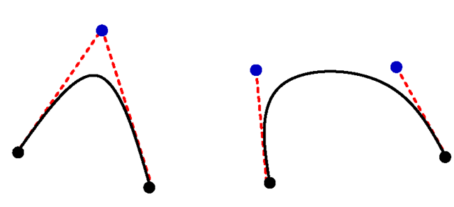
In the case of a quadratic curve with one control point one can imagine the lines connecting the control point with the two endpoints. The connecting lines are the tangents of the quadratic curve in the two endpoints. Figure 2.7 illustrates the definition of a quadratic curve on the left-hand side. The quadratic curve is given by two endpoints and one control point through which the curve does not pass. The tangents in the endpoints are also shown here as dotted lines. For a cubic curve as shown on the right-hand side of the figure, the tangents in the two endpoints can be defined independently by the two control points.
Fig. 2.6 A self-overlapping, a nonconvex and a convex polygon
Fig. 2.7 Definition of quadratic and cubic curves
Fig. 2.8 Fitting a cubic curve to a line without sharp bends
When fitting quadratic or cubic curves together in order to form a longer, more complicated curve, it is not sufficient to simply use the endpoint of the previous curve as a starting point for the next curve. The resulting joint curve would be continuous, but not smooth, i.e., sharp bends might occur. In order to avoid sharp bends, the tangent of the endpoint of the previous curve and the following curve must point into the same direction. This means the endpoint, which is equal to the starting point of the next curve, and the two control points defining the two tangents must be collinear. This means they must lie on the same line. Therefore, the first control point of a succeeding curve must be on the line defined by the last control and endpoint of the previous curve.
In the same way a curve can be fitted to a line without causing a sharp bend by locating the first control point on the prolongation of the line. Figure 2.8 illustrates this principle.
Other important curves in computer graphics are circles, ellipses and circular and elliptic arcs.
In the same sense as polygons, circles and ellipses define areas. Areas are bounded by a closed curve. When only the shell or margin of the area should be drawn, there is no difference to drawing arbitrary curves. In contrast to lines and simple curves, areas can be filled by colours and textures. From the algorithmic point of view, filling of an area is very different from drawing curves.
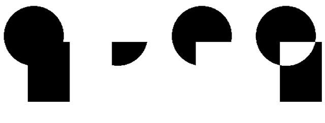
Fig. 2.9 Union, intersection, difference and symmetric difference of a circle and a rectangle
Axes-parallel rectangles, whose sides are parallel to the coordinate axes, play an important role in computer graphics. Although they can be understood as special cases of polygons, they are simpler to handle since it is already sufficient to specify two opposing vertices.
Instead of specifying a polygon or the boundary directly in order to define an area, it is sometimes more convenient to construct a more complicated area by combining previously defined areas using set-theoretic operations. The most important operations are union, intersection, difference and symmetric difference. The union joins two areas to a larger area whereas their intersection consists of the part belonging to both areas. The difference of an area with another removes all parts from the first area that also belong to the second area. The symmetric difference corresponds to a pointwise exclusive OR-operation applied to the two areas. The symmetric difference is the union of the two areas without their intersection. Figure 2.9 shows the results of applying these operations to two areas in the form of a circle and a rectangle.
Geometric transformations like scalings will be discussed in Sect. 2.5. They provide another way of constructing new areas from already existing ones.
Basic Geometric Objects in Java 2D
All methods for generating geometric objects as they were described in the previous section are also available within the Java 2D framework. The abstract class Shape with its various subclasses allows the construction of various two-dimensional geometric objects. Vector graphics is used to define Shape objects, whose realvalued coordinates can either be given as float- or double-values. Shapes will not be drawn until the draw or the fill method is called with the corresponding Shape as argument in the form graphics2d.draw(shape) or graphics2d.fill(shape), respectively. The draw method draws only the margin or circumference of the Shape object, whereas the whole area defined by the corresponding Shape object is filled when the fill method is called.
The abstract class Point2D for points is not a subclass of Shape. Points cannot be drawn directly. If one wants to draw a point, i.e., a single pixel, then a line from this point to the same point can be drawn instead. Objects of the class Point2D are mainly used to specify coordinates for other geometric objects. In most cases, it is also possible to define these coordinates also directly by two single values determining the x- and the y-coordinate. Therefore, the class Point2D will not occur very often in the example programs. The abstract class Point2D is extended by the two
classes Point2D.Float and Point2D.Double. When using the abstract class Point2D it is not necessary to specify whether coordinates are given as float-or double-values. The same concept is also used for most of the other geometric objects.
The elementary geometric objects in Java 2D introduced in the following extend the class Shape, so that they can be drawn by applying one of the methods draw or fill.
The abstract class Line2D defines lines. One way to define a line from point (x\,y\) to point (x2,y2) is the following:
Line2D.Double line = new Line2D.Double(x1,y1,x2,y2); The parameters x1, y1, x2 and y2 are of type double. Similarly, Line2D.Float requires the same parameters, but of type float. It should be emphasised again that the defined line will not yet be drawn. Only when the method g2d.draw(line) is called, will the line appear on the screen.
Analogously to lines, quadratic curves are modelled by the abstract class QuadCurve2D. The definition of a quadratic curve requires two endpoints and one control point. The quadratic curve is constructed in such a way that it connects the two endpoints (x\,y\) and (x2,y2) and the tangents in the endpoints meet in the control point (crtlx, crtly), as illustrated by the left curve in Fig. 2.7. One way to define quadratic curves in Java 2D is the following:
Cubic curves need two control points instead of one in order to define the tangents in the two endpoints independently as shown by the right curve in Fig. 2.7. Java 2D provides the abstract class CubicCurve2D for modelling cubic curves. Analogously to the cases of lines and quadratic curves, CubicCurve2D.Double is a subclass of CubicCurve2D allowing to define a cubic curve in the following way:
The program CurveDemo.java demonstrates the usage of the classes Line2D.Double, QuadCurve2D.Double and CubicCurve2D.Double.
The class GeneralPath allows the construction not only of polylines, i.e., sequences of lines, but also mixed sequences of lines, quadratic and cubic curves in Java 2D. A GeneralPath starts in the origin of the coordinate system, i.e., in the point (0, 0). The class GeneralPath provides four basic methods for defining a sequence of lines, quadratic and cubic curves. Each method will append a corresponding line or curve to the endpoint of the last element in the sequence of the GeneralPath. The methods lineTo, quadTo and curveTo append a line, a quadratic and a cubic curve, respectively, as the next element in the sequence of the
Fig. 2.10 An example for a General Path
General Path. These methods are used within General Path in the same way as in Line2D, QuadCurve2D and CubicCurve2D except that the definition of the first endpoint of the line or curve is omitted since this point is already determined by the endpoint of the previous line or curve in the General Path. The coordinates of the points must be specified as float-values. In addition to these three methods for curves and lines, the class General Path also contains the method move To that allows to jump from the endpoint of the previous curve to another point without connecting the points by a line or curve. A General Path must always start with the method move To, defining the starting point of the general path.
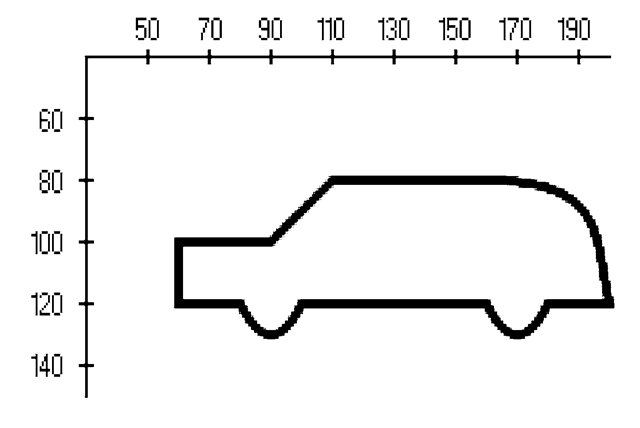
Figure 2.10 shows the outline of a car that was generated by the following
The coordinate system shown in Fig. 2.10 refers to the window coordinates, so that the y-axis points downwards. The complete class for drawing the car can be found in the example program GeneralPathCar.java.
An area can be defined by its boundary, which might be specified as a GeneralPath object. In addition to the class GeneralPath Java 2D also provides classes for axes-parallel rectangles and ellipses as basic geometric objects.
By the class Rectangle2D.Double, extending the abstract class Rectangle2D, an axes-parallel rectangle can be defined in the following way:
Fig. 2.11 An example for a rectangle and an ellipse
The rectangle is determined by its opposite corners (x, y) and (x + width,y + height) on the diagonal. Taking into account that the y-axis in the window where the rectangle will be drawn points downwards, a rectangle is defined whose upper left corner is located at the position (x, y) and whose lower right corner is at (x + width,y + height). Figure 2.11 shows a rectangle on the left-hand side that was defined by
It should be emphasised again that this constructor will only define the rectangle in the same way as for all other Shape objects that were introduced so far. It is still necessary to call the method g2d.draw(r2d) in order to show the rectangle in the corresponding window.
In the same way as rectangles, axes-parallel ellipses can be defined in Java 2D. An ellipse is determined by its bounding rectangle which can be specified with the same parameters as Rectangle2D objects. The ellipse shown in Fig. 2.11 on the right-hand side was generated by
For illustration purposes the bounding rectangle that was used to generate the ellipse is also shown in Fig. 2.11. The figure was generated by the class RectangleEllipseExample.java.
A circle is a special case of an ellipse, where the bounding rectangle is a square. A circle with centre point (x, y) and radius r can be generated by
With the class Arc2D elliptic arcs and, of course, circular arcs can be defined.
• rect2D specifies the bounding rectangle of the corresponding ellipse in the form of a Rectangle2D.
Fig. 2.12 An arc of an ellipse, a segment and an arc with its corresponding chord
• start is the angle where the arc is supposed to start relative to the bounding rectangle viewed as a square. The angle is given as a float-value in terms of degrees.3 The angle corresponds to the angle with the x-axis only in the special case when a circular arc is defined, i.e., when the bounding rectangle is a square. Otherwise, the angle is determined relative to the rectangle. For example, a starting angle of 45° means that the starting point of the arc lies on the connecting line from the centre of the rectangle to its upper right corner.
• extend is the opening angle of the arc, i.e., the arc extends from the start angle start to the angle start + extend. Analogously to the start angle, extend corresponds to the true angle of the arc only in the case of a circular arc. The angle start + extend is again interpreted relative to the bounding rectangle in the same way as start. extend must also be specified as a float-value in degrees.
• type can take one of the three values Arc2D.OPEN, Arc2D.PIE and Arc2D.CHORD, specifying whether only the arc itself, the corresponding segment or the arc with the chord of the ellipse, respectively, should be constructed. Figure 2.12 shows from left to right an arc of an ellipse, a segment and an arc together with the corresponding chord. In all cases a starting angle of 45° and an opening angle of 90° were chosen. For illustration purposes the bounding rectangle is also shown in the figure. One can see clearly that the arc starts on the intersection of the ellipse with the line from the centre of the bounding rectangle to its upper right corner, according to the choice of the starting angle of 45°. Obviously, the line defined by the centre point of the rectangle and the starting point of the ellipse meets the x-axis in a smaller angle than 45° since a flat, but long bounding rectangle was chosen. The same applies to the opening angle. The actual opening angle is not 90°, but it corresponds to the angle between the lines from the centre of the bounding rectangle to its upper right and to its upper left corner. An example for using the class Arc2D can be found in the file ArcExample.java, which was also used to generate Fig. 2.12.
An area can be defined as a rectangle, an ellipse or in the form of a GeneralPath. At the end of Sect. 2.3 a technique for defining areas based on the set-theoretic operations union, intersection, set difference and symmetric difference was explained. Applying these operations to already defined areas, new shapes of areas can be defined. Java 2D offers the class Area for this purpose. From a Shape object s, for instance a Rectangle2D, anEllipse2D, a closed GeneralPath or an Arc2D, representing the segment of an ellipse or an ellipse arc with its chord, an Area object with the same outline can be defined by Area a = new Area(Shape s);
The above-mentioned set-theoretic operations can be applied to such Area objects to generate new areas. Given two Area objects areaA and areaB, the following methods are available, implementing the corresponding set-theoretic operations.
• areaA.add(areaB) computes the union of areaA and areaB.
• areaA.intersect(areaB) computes the intersection of areaA and areaB.
• areaA.subtract(areaB) yields areaA without the parts lying in areaB, i.e., their difference.
• areaA.exclusiveOr(areaB) constructs the union of areaA and areaB without their intersection, i.e., their symmetric difference.
The Area object areaA contains the result of the application of the corresponding set-theoretic operation. An Area object can be used as an argument of the methods draw, which will only draw the outline of the area, and fill, which will fill the whole area, in the same way as these methods are used for Shape objects. The file AreaExample.java, which was also used to generate Fig. 2.9 on page 15, demonstrates the use of Area objects.


![tmpc009-12_thumb[2] tmpc009-12_thumb[2]](http://what-when-how.com/wp-content/uploads/2012/06/tmpc00912_thumb2_thumb.png)
![tmpc009-13_thumb[2] tmpc009-13_thumb[2]](http://what-when-how.com/wp-content/uploads/2012/06/tmpc00913_thumb2_thumb.png)

![tmpc009-15_thumb[2] tmpc009-15_thumb[2]](http://what-when-how.com/wp-content/uploads/2012/06/tmpc00915_thumb2_thumb.png)

![tmpc009-17_thumb[2] tmpc009-17_thumb[2]](http://what-when-how.com/wp-content/uploads/2012/06/tmpc00917_thumb2_thumb.png)

