Geometric Transformations in Java 3D
Instances of the class Transform3D store three-dimensional transformations as matrices in homogeneous coordinates similarly to the class AffineTransform for two-dimensional affine transformations. The constructor Transform3D tf = new Transform3D(); generates the identity transformation corresponding to the unit matrix. The method tf.rotX(theta); defines tf as a rotation by the angle theta around the x-axis. Correspondingly, the methods rotY and rotZ specify rotations around the y – and the z-axis, respectively.
The method
tf.setScale(new Vector3f(x,y,z)); leads to the scaling S(x, y, z).
The method tf.setScale(factor) defines a scaling with the same scaling factor factor for the x-, y – and z-direction.
An arbitrary transformation can be specified by tf.set(matrix) where matrix is a one-dimensional double-array with 16 values specifying the entries in the matrix. It should be noted that the last row of the matrix can also be defined. Usually, the last row should be (0, 0,0,1). tf.get(matrix) stores the matrix associated with the transformation tf in the (one-dimensional) doublearray matrix.
The composition of transformations in the sense of matrix multiplication can be realised by tf.mul(tf1,tf2) or tf1.mul(tf2).Inthe first case, the transformation resulting from the composition of the transformations tf1 and tf2 is stored in the transformation tf, in the latter case in the transformation tf1. Since the composition of transformations is carried out in Java 3D in the same way as matrix multiplications are computed, the rightmost transformation will be applied first. This means that the resulting transformation corresponds to first applying the transformation tf2 and then tf1.
The Scenegraph
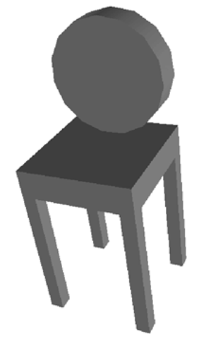
For modelling a three-dimensional scene, geometric objects have to be defined and positioned in the scene. Techniques for constructing and modelling geometric objects are discussed in Chap. 6. In addition to defining elementary objects like boxes, spheres, cylinders or cones, there are more sophisticated techniques for modelling complex objects. Complex objects are usually composed of simpler smaller objects. The chair in Fig. 5.2 is an object that is composed of elementary geometric objects. The legs and the seat are boxes, the backrest is a cylinder.
In order to model the chair, the corresponding elementary geometric objects must be defined with the intended admeasurements and then these objects have to be positioned correctly. To position an object correctly, suitable transformations need to be applied to it. If the whole chair should occur at another position in the scene, for instance farther to the right, then a corresponding transformation must be applied to all its parts. For an object designer or a programmer, it would be a quite tedious task to ensure explicitly that this transformation is applied to every single part, especially when much more complicated objects than the simple chair are considered. Therefore, instead of thinking of each particular geometric object as an independent instance, a scenegraph is defined in which the objects are grouped in a hierarchy of transformation groups. In the case of the chair, the chair itself would be a transformation group on its own, combining the legs, the seat and the backrest into one group. A transformation applied to the transformation group of the chair will automatically be applied to all members of the transformation group. In this way, the whole chair can be positioned anywhere in the scene by an arbitrary transformation without the need to state explicitly that this transformation should be applied to all parts of the chair.
Fig. 5.2 A chair constructed with elementary geometric objects
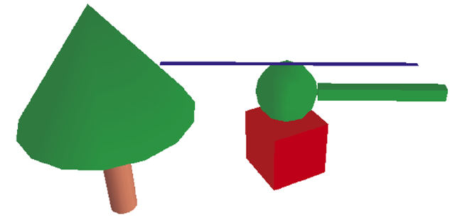
To explain the concept of scenegraphs better, a slightly more complex example than the simple chair is considered. The scene contains a very simplified helicopter positioned on a cubical platform. A simplified tree also belongs also to the scene that is shown in Fig. 5.3.
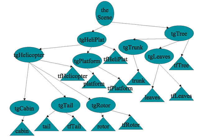
A possible scenegraph of this scene is shown in Fig. 5.4. The root of the scene-graph has two child nodes. Both are transformation groups. Elementary geometric objects, other transformation groups or transformations can be assigned to a transformation group as child nodes. The transformation groups tgHeliPlat and tgTree represent the helicopter including the platform and the tree, respectively. Both of these transformation groups have a transformation as a direct child node. The transformation tfHeliPlat positions the helicopter together with the platform at the desired place in the scene, the transformation tfTree does the same for the tree.
The transformation group tfTree also has two transformation groups as child nodes. tgTrunk stands for the trunk of the tree and tgLeaves for the treetop. The transformation group has only one child node in the form of an elementary geometric object tgTrunk, a cylinder that is generated in the origin of the coordinate system. The transformation group tgLeaves consists of the elementary geometric object leaves in the form of a cylinder and a transformation tfLeaves. This transformation moves the treetop which was also generated in the origin of the coordinate system to the top of the tree trunk.
The transformation group tgHeliPlat for the helicopter and the platform is built in a similar way. It contains a transformation for positioning the platform together with the helicopter correctly in the scene, and there are two other child nodes, the individual transformation groups tgHelicopter and tgPlatform for the helicopter and the platform, respectively. The helicopter transformation group itself has a transformation tfHelicopter to position the helicopter on top of the platform and three other transformation groups containing elementary geometric objects. The cockpit of the helicopter is a sphere, the tail and the rotor blade are boxes. The transformations tfTail and tfRotor are needed to position the tail at the end and the rotor blade on top of the cockpit.
Fig. 5.3 A scene composed of various elementary objects
Fig. 5.4 The scenegraph for Fig. 5.3
Elementary Geometric Objects in Java 3D
To be able to show objects of a three-dimensional scene, it is not sufficient to outline their geometry only. It is also necessary to specify what the surface of the object looks like. A colour or a texture must be assigned to the surface. Even this is not sufficient for more realistic images. Reflection properties of the surface, e.g., how shiny it is, are also needed. The appearance of the surface of an object is defined in the class Appearance in Java 3D. More details of the class Appearance will be explained in connection with illumination in Chap. 8. Here, the focus is on basic geometry and transformations. Therefore, a simplified default appearance is used until Chap. 8. A simple instance of Appearance is generated in the following way:
The method setToMyDefaultAppearance is not a standard method of Java 3D. It was written for the purpose of this topic. The method can be found in some of the example programs, for instance in the class StaticSceneExample.java. The method assigns a desired colour given by an instance of the class Color3f to the Appearance myApp. The colour is defined by the three float-values r, g, b e [0,1] specifying the intensities for red, blue and green.
After an Appearance myApp has been created, the following elementary geometric objects can be defined within Java 3D. In the following, all floating point values are of the type float, unless otherwise stated.
A box is generated by
Box xyzBox = new Box(x,y,z,myApp);
The box has the size (2x) x (2y) x (2z) and is centred in the origin of the coordinate system. Unless specific transformations are applied or the viewpoint of the viewer in the scene is changed, the x-axis in Java 3D points to the right, the y-axis upwards and the z-axis in the direction forward to the viewer.
Sphere rSphere = new Sphere(r,myApp); defines a sphere with radius r and midpoint in the origin of the coordinate system. A cylinder with radius r and height h whose centre point is again in the origin of the coordinate system is generated by
Cylinder rhCylinder = new Cylinder(r,h,myApp);
The cylinder is positioned in such a way that the axis along its height coincides with the y-axis. This means the cylinder extends h/2 units above and below the x/z-plane.
In the same way a cone with radius r and height h is constructed by
Cone rhCone = new Cone(r,h,myApp);
The cone is positioned in the same way as the cylinder centred around the y-axis with its tip h/2 units above the x/z-plane.
The Scenegraph in Java 3D
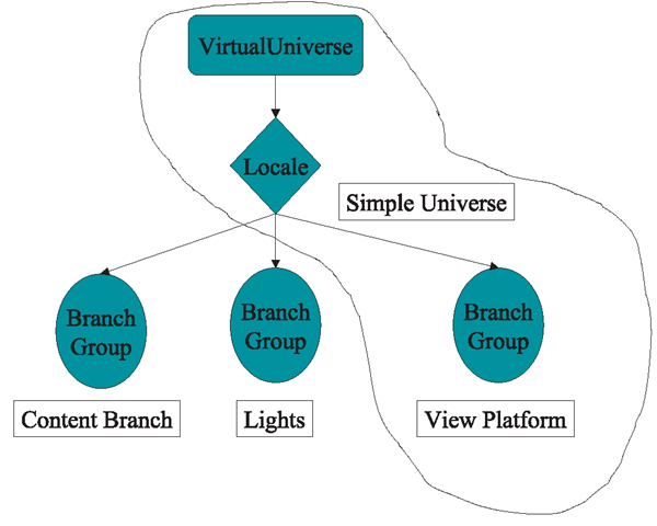
Java 3D offers a complex scenegraph with a variety of different structures. Most of the programs in this topic are based on a division into three branches. One branch is for modelling the objects within the scene, their positions and possible animated movements. Another branch is responsible for illumination, providing one or more light sources. The third branch takes care of the view of the scene. The position of the viewer and the direction of his view belong to this branch. Information about his field of view, like the angle or how far he can see, is also found in this branch.
Fig. 5.5 The overall scenegraph for Java 3D
Even options like 3D-viewing with a head-mounted display providing different images for the left and right eye could be incorporated in this branch. The class SimpleUniverse in Java 3D simplifies the definition of this branch, the so-called view platform. The parameters are set to default values and the programmer is freed from providing detailed definitions. There are also methods to modify the default parameter settings, which will be introduced later on. For the purpose of this topic, the options provided by the class SimpleUniverse are sufficient. In later sections, more details about the parameter settings in SimpleUniverse and their modifications will be explained. Since this section is only concerned with modelling of geometric objects, the default settings of SimpleUniverse are simply taken as they are. Figure 5.5 shows the general scenegraph for Java 3D and the role of the class SimpleUniverse, making the programming task a little easier.
All Java 3D classes in this topic have the same basic structure, except for small modifications for specific applications. As a first step, some standard Java and Java 3D packages need to be imported. This is usually done by
In special cases additional classes or packages are required. For the representation on the computer screen an instance of the Java class JFrame is used. The corresponding class with the Java 3D program must therefore extend the class JFrame.
The class with the Java 3D program will also need an instance of the class Canvas3D as one of its attributes.
The constructor of the class has the following structure:
The first method setDefaultCloseOperation has nothing to do with Java 3D. It is only for closing the display window in which the virtual scene will be shown and for terminating the program. Afterwards the SimpleUniverse is built with its default settings. The method createSceneGraph must be implemented individually for each program or scene. All geometric objects, information about their surfaces and dynamic changes can be incorporated in this method, representing the content branch in Fig. 5.5. Further details about the content branch will be provided later on in this section. The method addLight defines the illumination of the scene and it can also be implemented differently for each virtual scene, depending on whether the scene is an open air scenario with sunlight or located in a room with artificial light. The details of this method and illumination are explained in Chap. 8. The last four lines of the constructor are again concerned with the display window, not with Java 3D specific tasks. They determine the title of the window, its size as well as its layout, and display the window.
It is very useful to include the following three lines of code after the method addLight is called:
These three lines enable navigation through the scene using the mouse. Moving the mouse while pressing its left button, the scene is rotated. The right mouse button is for moving through the scene. Zooming can be achieved by pressing the ALT-key together with the left mouse button and moving the mouse. How this is actually realised from the computer graphics point of view will be described in Sect. 5.8.
Once the methods createSceneGraph and addLight have been implemented, all that has to be done is to call the constructor of the corresponding created class in the main method.
How to implement the method createSceneGraph, depending on the specific scene to be modelled, shall be demonstrated with the example in Fig. 5.3 on page 107. The associated scenegraph is shown in Fig. 5.4 on page 107. Only the construction of the tree will be explained in detail here. The helicopter together with the platform is built in the same way. The complete program code can be found in the class StaticSceneExample.java.
As a first step the tree trunk is created. Before an instance of the corresponding geometric object can be defined, it is necessary to specify a suitable Appearance with a brown colour for the tree trunk.
Then the tree trunk can be defined as a cylinder with height 0.4 and radius 0.05, centred in the origin of the coordinate system.
Afterwards, an instance tgTrunk of the class TransformGroup is generated and the tree trunk is assigned to this transformation group by the method
After the transformation group has been created for the tree trunk, the treetop can be handled in a similar manner. Since the treetop should have a green instead of a brown colour, a new instance greenApp of the class Appearance has to be generated. In the example program, this Appearance has already been created for the cockpit of the helicopter. The treetop is generated as a cone centred in the origin of the coordinate system.
The treetop should be positioned on top of the trunk. This means, it must be lifted by half the height of the tree trunk plus half of the height of the treetop. It is only half the height for both objects since the corresponding cylinder and cone are centred in the origin of the coordinate system. The following transformation is defined for this purpose:
Now a transformation group can be generated for the treetop. Since this transformation group has to incorporate the above translation, it is not sufficient to use the default constructor without parameters as in the case of the tree trunk. Otherwise both the trunk and the treetop would remain centred around the origin of the coordinate system. The corresponding constructor for the transformation group tfLeaves will be called with the previously defined translation as its argument. Then the tree-top can be assigned to the transformation group by the method addChild.
So far, the tree has been constructed correctly, but its trunk is centred around the origin of the coordinate system. This might not be the desired position in the scene. In order to position the whole tree, another transformation group has to be defined. As a first step, a suitable transformation must be defined, then the transformation group can be created with this transformation, and finally the single transformation groups tgTrunk and tgLeaves for the trunk and the treetop can by assigned to the transformation group for the whole tree:
The advantage of this hierarchical structure becomes obvious here. Once the tree has been constructed, i.e., once the treetop is positioned correctly on top of the trunk, the whole tree can be positioned anywhere in the scene without worrying about the fact that the corresponding transformation has to be applied to all single parts of the tree. With this hierarchical structure, the two transformations—one for positioning the treetop on top of the trunk and one for positioning the tree itself—are automatically applied correctly to the treetop. Especially, more complex objects built from more than just two elementary geometric objects can be handled and controlled in a very comfortable way in a scenegraph. When the scene is displayed, the underlying rule for the calculations is very simple. The scenegraph has to be traversed and all transformations along a path to a geometric object have to be applied to this object.
It is also possible to use the same object, for instance the tree, more than just once in the same scene. The class Link is required for this, which will be explained in Sect. 9.2.
The helicopter and the platform are built in the same way based on the hierarchical structure shown in the scenegraph in Fig. 5.4 on page 107. In this case, not only translations are applied to position the objects, but also a rotation in addition to the platform in order to turn it slightly. In principle, any transformation defined directly by a corresponding method or matrix, or specified as a composition of elementary transformations can be assigned to a transformation group. For the purpose of positioning an object, combinations of translations and rotations are sufficient. When objects should be enlarged or made smaller, scalings are required.
After all transformation groups for a scene have been created and organised in a suitable hierarchical structure, the transformation groups on the top of the hierarchical structure must be assigned to the scene itself. In the example of the helicopter scene, there are only two top transformation groups: tgTree for the tree and tgHeliPlat for the helicopter together with the platform. For the details of the construction of the transformation group tgHeliPlat the reader is referred again to the program StaticSceneExample.java.
The BranchGroup, containing the scene, can now be generated. The transformation groups tgTree and tgHeliPlat are assigned to the BranchGroup by the method addChild. Afterwards the BranchGroup should be compiled by the method compile and assigned to the SimpleUniverse by calling the method
Figure 5.3 on page 107 was generated with the class StaticSceneExample.java. For better viewing purposes, the scene was slightly tilted by mouse movements. Also a white background instead of the default black background in Java 3D was added to the scene. How to change the background colour or add a background image will be explained in more detail in Chap. 8.


![tmpc009-227_thumb[2] tmpc009-227_thumb[2]](http://what-when-how.com/wp-content/uploads/2012/06/tmpc009227_thumb2_thumb.png)

![tmpc009-229_thumb[2] tmpc009-229_thumb[2]](http://what-when-how.com/wp-content/uploads/2012/06/tmpc009229_thumb2_thumb.png)
![tmpc009-232_thumb[2] tmpc009-232_thumb[2]](http://what-when-how.com/wp-content/uploads/2012/06/tmpc009232_thumb2_thumb.png)
![tmpc009-233_thumb[2] tmpc009-233_thumb[2]](http://what-when-how.com/wp-content/uploads/2012/06/tmpc009233_thumb2_thumb.png)
![tmpc009-234_thumb[2] tmpc009-234_thumb[2]](http://what-when-how.com/wp-content/uploads/2012/06/tmpc009234_thumb2_thumb.png)
![tmpc009-235_thumb[2] tmpc009-235_thumb[2]](http://what-when-how.com/wp-content/uploads/2012/06/tmpc009235_thumb2_thumb.png)
![tmpc009-236_thumb[2] tmpc009-236_thumb[2]](http://what-when-how.com/wp-content/uploads/2012/06/tmpc009236_thumb2_thumb.png)
![tmpc009-237_thumb[2] tmpc009-237_thumb[2]](http://what-when-how.com/wp-content/uploads/2012/06/tmpc009237_thumb2_thumb.png)
![tmpc009-239_thumb[2] tmpc009-239_thumb[2]](http://what-when-how.com/wp-content/uploads/2012/06/tmpc009239_thumb2_thumb.png)
![tmpc009-241_thumb[2] tmpc009-241_thumb[2]](http://what-when-how.com/wp-content/uploads/2012/06/tmpc009241_thumb2_thumb.png)
![tmpc009-242_thumb[2] tmpc009-242_thumb[2]](http://what-when-how.com/wp-content/uploads/2012/06/tmpc009242_thumb2_thumb.png)
