This topic and all following ones are devoted to methods and problems in connection with the representation of three-dimensional scenes. Before the topics are discussed in more detail, the following section provides a short overview on which tasks and problems occur on the way from the real world or an abstract 3D model to the representation on the computer screen or another output device.
From a 3D World to a Model
Before anything can be drawn on the computer screen, a three-dimensional virtual world of objects must be defined and stored in the computer. The same principle applies even to two-dimensional virtual worlds. Geometric objects like rectangles, circles or polygons must be specified before they can be drawn. The three-dimensional virtual world can contain much more than what will be displayed in one moment on the computer screen. The virtual world might consist of a building or even a city, perhaps a larger landscape, but the viewer will only see a small part of this virtual world, for instance only a single room in a building. Of course, the viewer can move around in the virtual world and explore it. But in the above examples he will never see the whole virtual world in one single image.
The first step consists of modelling the objects of the virtual world. The description of a three-dimensional object must contain information about its geometry but also properties of its surface. What is the object’s colour? Is the surface shiny or dull?
There are two different approaches for modelling the geometry of objects. In many applications of computer graphics, the objects do not have existing counterparts in reality. This is the case for fantasy worlds of computer games as well as for models of concept cars or possible future buildings that have not been built yet and might or might not be built in the future. In these cases, the designer or programmer of the virtual world needs methods for constructing and modelling threedimensional virtual objects. Even if existing objects are to be modelled, such construction and modelling techniques might be necessary. For existing buildings or furniture some principal measurements like height or width might be available. But such information is by far not enough to generate a realistic representation of the objects. The objects might, for instance, have rounded corners.
In other cases, detailed measurements of the geometric structure of objects might be available. 3D laser scanners provide detailed information about an object’s surface geometry. However, the raw data coming from 3D laser scanners are not suitable for direct use in virtual worlds of computer graphics. They are usually processed further automatically with additional manual corrections to yield simpler surface models. The same applies to techniques for measuring inner geometric structures. Steel girders in buildings or bridges are an example where such techniques are applied. Another important and quickly developing application field in this context is medical informatics. X-ray, ultrasonic and tomography techniques provide information about skeletal and tissue structures from which 3D models of bones and organs can be derived.
The first step in computer graphics is therefore the creation of a computer model of the virtual world, either manually by a designer or programmer, or automatically derived from measurements. To represent a specific part of this virtual world, the viewer’s position and direction of view in the virtual world must be defined. This also includes his field of view, the viewing angle and the distance he can see. In this way, a three-dimensional clipping region is defined so that only objects within the region need to be considered for rendering.
However, so far the image will remain black when no lights are added to the virtual world. The sources of light, their locations as well as their characteristics must be defined. Characteristics are for instance the colour of the light or whether the light shines only in one direction like a spotlight. Only with this information is it possible to compute how much light a single object receives, whether it is in the shadow or in the bright light.
Determining which objects are visible and which objects are hidden by others within the clipping region is another problem.
Finally, additional special effects might be needed in the scene like fog, smoke or reflections.
Geometric Transformations
As in the two-dimensional case, geometric transformations also play a crucial role in three-dimensional computer graphics.
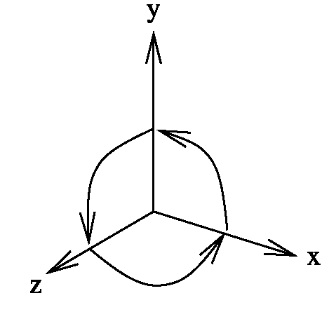
Three-dimensional coordinates in this topic will always refer to a right-handed coordinate system. Using the thumb of the right hand for the x-axis, the forefinger for the y-axis and the middle finger for the z-axis, one obtains the correct orientation of the coordinate system. In a right-handed coordinate system the x-axis is mapped to the y-axis by a positive, i.e., anticlockwise, rotation of 90° around the z-axis. The y-axis is mapped by a positive rotation of 90° around the x-axis to the z-axis and the z-axis is transformed to the x-axis by a positive rotation of 90° around the y-axis to the x-axis. Figure 5.1 illustrates aright-handed coordinate system.
Fig. 5.1 A right-handed coordinate system
A rotation by a positive angle around an oriented axis in the three-dimensional space refers to an anticlockwise rotation for a viewer to whom the axis points. This definition of positive rotations is consistent with rotations in the two-dimensional x/y-plane around the origin of the coordinate system when it is interpreted as a rotation around the z-axis. In order to determine whether a rotation is positive or negative, one can also apply the right-hand rule. When the thumb of the right hand points in the same direction as the rotation axis and the other fingers form a fist, then the bent fingers indicate the direction of positive rotation.
In Sect. 2.6 homogeneous coordinates were introduced in order to be able to express all affine transformations in the plane in terms of matrix multiplications. The same principle of extending the coordinates by an additional dimension is also applied in the case of points and affine transformations in the three-dimensional space. A point in the three-dimensional space R3 is represented by four coordinates (Xe, y, z, w) where w = 0. The point (Xe, y, z, w) in homogeneous coordinates stands for the point in Cartesian coordinates. The point (x,y,z) e R3 can be represented in homogeneous coordinates in the form (x,y,z, 1). This is, however, not the only way. Any representation in the form (x · w, y · w, z · w, w) with w = 0 encodes the same point as well.
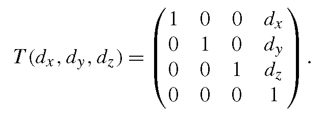
A translation by the vector (dx,dy,dz)T can be written as a matrix multiplication in homogeneous coordinates in the following way:
The translation matrix is
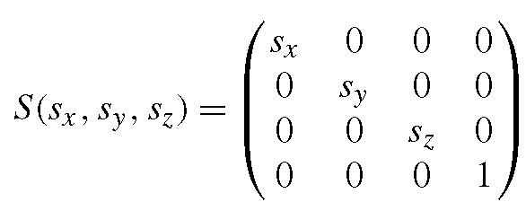
A scaling by the factors sx, sy, sz is given by
with
as scaling matrix.
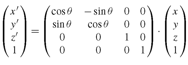
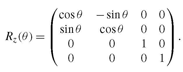
In the two-dimensional case, it was sufficient to consider rotations around the origin of the coordinate system. By applying suitable transformations in addition, rotations around arbitrary points can be defined. In the three-dimensional case, instead of a centre point a rotation axis must be specified. The three elementary rotations in the three-dimensional space are the rotations around the coordinate axes. A rotation around the z-axis by the angle θ in homogeneous coordinates is given by
with the rotation matrix
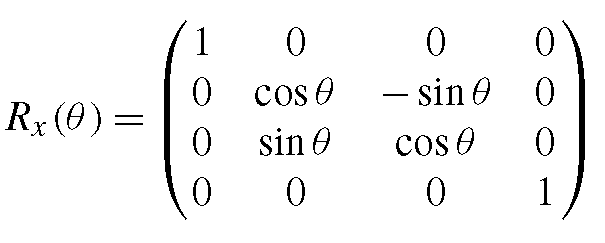
This rotation matrix corresponds to the one already known from the two-dimensional case. It is only extended by the z-dimension. A rotation around the z-axis leaves the z-coordinates of a point unchanged. The matrices for rotations around the x- and the y-axis can be obtained from the above matrix by exchanging the roles of the corresponding axes so that a rotation around the x-axis by the angle θ is described by the matrix
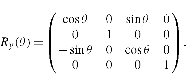
and a rotation around the y-axis by the angle θ by the matrix
By combining these three elementary rotations around the coordinate axes with suitable translations, a rotation around an arbitrary axis and an arbitrary angle can be realised. Given an arbitrary rotation axis and a rotation angle, the first step is to apply a translation T(dx,dy,dz), shifting the rotation’s axis in such a way that it passes through the origin of the coordinate system. Afterwards, a rotation around the z-axis is carried out, mapping the translated rotation axis to the y/z-plane. Then this axis can be transformed into the z-axis by a rotation around the x-axis. Now the original rotation can be carried out as a rotation around the z-axis by the angle θ. Finally, all previous transformations have to be reversed again. Altogether, the transformation
is obtained. It should be noted that the transformations are carried out like matrix multiplications from right to left.
In all above-mentioned transformation matrices the last row is (0,0, 0, 1). Applying matrix multiplication to such matrices preserves this property.
In the two-dimensional case there is exactly one transformation matrix that maps three noncollinear1 points to three other noncollinear points. Correspondingly, in the three-dimensional case there exists exactly one transformation matrix that maps four noncoplanar2 points to four other noncoplanar points. Given four noncoplanar points P1, p2, p3, p4 e R3 and the target points p^, p2, p3, p4, the transformation matrix is obtained by solving the system of linear equations
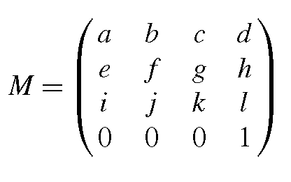
The matrix
in homogeneous coordinates must be derived from the four vector equations (5.1), each of them representing three3 equations, one for the x-, the y – and the z-component, from which the twelve parameters of the matrix M can be calculated.
In this sense, transformations can be interpreted as changing from one coordinate system to another. This property will be used later on, for instance to view the same scene from different perspectives.
Java 3D
Unlike Java 2D, Java 3D does not belong to the standard Java framework and needs to be installed separately. Information about where Java 3D can be downloaded freely and how to install it can be found at the end of this topic and on the web page of the topic.
It is not the intention of this topic to provide a complete introduction and overview on Java 3D. The main goal is to demonstrate how the computer graphics concepts introduced in this topic can be used in practical examples in a quick and easy way. Some of the introduced concepts go even further than Java 3D at its present state to outline further perspectives. Nevertheless, the small selection of Java 3D classes and methods explained in this topic will equip the reader with enough knowledge to get started with Java 3D and to write animated 3D graphics programs with interaction. Readers who would like to learn Java 3D in further detail are referred to topics like [2-6], the Java 3D API documentation and the Java 3D tutorial. Special topics, like the design of 3D user interfaces with Java 3D, can be found in [1].
