2.5
Based on Eqs. (2.3), (2.6), and (2.10) through (2.14), stator current, torque, input and output power, efficiency, and power factor of an induction motor can easily be computed. The input power, Pin, efficiency, t|, and power factor, PF, can be expressed as
![]()
![]()
and
![]()
![tmp2B7-67_thumb[1] tmp2B7-67_thumb[1]](http://lh3.ggpht.com/_X6JnoL0U4BY/S1hakrdYTNI/AAAAAAAAIAk/_ZZszcYUeHQ/tmp2B767_thumb1_thumb.png?imgmax=800)
and the Pin to 5in ratio is equal to the cosine of phase shift between the sinusoidal waveforms of stator voltage and current.
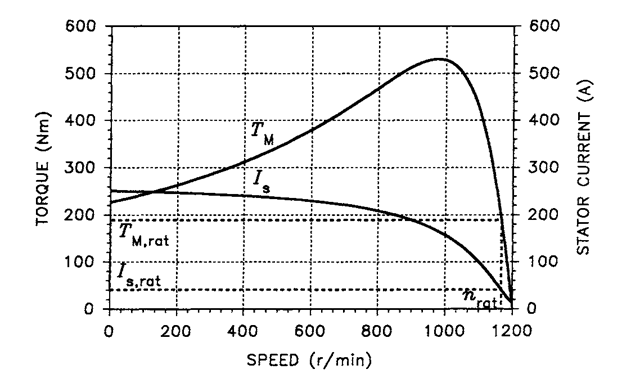
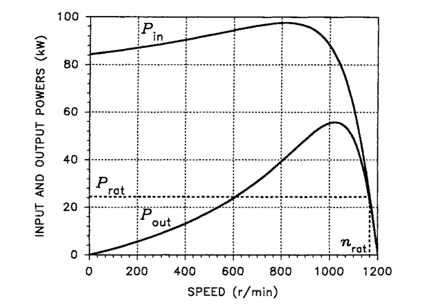
For illustration purposes, a 30-hp induction motor, whose data (some of which have not yet been explained) are listed in Table 2.1, will be used throughout the topic. With the rated voltage and frequency, the torque and stator current, input and output power, and efficiency and power factor of this motor are shown in Figures 2.18 through 2.20, respectively. All these variables are plotted as functions of the r/min speed, n. The latter is related to the angular velocity, o>M, of the motor, expressed in rad/s, as
![tmp2B7-68_thumb[1] tmp2B7-68_thumb[1]](http://lh4.ggpht.com/_X6JnoL0U4BY/S1hal7e0yUI/AAAAAAAAIAs/geSi-7m1jPs/tmp2B768_thumb1_thumb.png?imgmax=800)
The rated speed, nrat; torque, TMm; current, 7Srat; and power, Prat, are marked by a broken line to highlight the rated conditions of the motor. The rated torque, current, and powers are much lower than their maximum
TABLE 2.1 Parameters of the Example Motor
| Parameter | Symbol | Value |
| Rated power | ”rat | 30 hp (22.4 kW) |
| Rated stator voltage* | v ‘ s.rat |
230 V/ph |
| Rated stator current** | ‘s,rat | 39.5 A/ph |
| Rated frequency | /rat | 60 Hz |
| Rated slip | ^rat | 0.027 |
| Rated speed | “rat | 1168 r/min |
| Rated torque | 7M,rat | 183 Nm |
| Number of pole pairs | P | 6 |
| Stator connection | delta | |
| Stator resistance | Rs | 0.294 fl/ph |
| Stator leakage reactance at 60 Hz | Xis | 0.524 fl/ph |
| Stator reactance at 60 Hz | *s | 15.981 ft/ph |
| Stator inductance | i-s | 0.0424 H/ph |
| Rotor resistance | *r | 0.156 ft/ph |
| Rotor leakage reactance at 60 Hz | X* | 0.279 ft/ph |
| Rotor reactance at 60 Hz | xr | 15.736 O/ph |
| Rotor inductance | 0.0417 H/ph | |
| Magnetizing reactance at 60 Hz | xm | 15.457 n/ph |
| Magnetizing inductance | 0.041 H/ph | |
| Rotor mass moment of inertia | 0.4 kg.m2 |
![tmp2B7-69_thumb[1] tmp2B7-69_thumb[1]](http://lh6.ggpht.com/_X6JnoL0U4BY/S1hatVNQnjI/AAAAAAAAIA0/jOnekbQTTJ4/tmp2B769_thumb1_thumb.png?imgmax=800)
values. As seen in Figure 2.20, the rated speed offers the best tradeoff between the efficiency and power factor of the motor.

FIGURE 2.18 Stator current and developed torque versus speed of the example motor.

FIGURE 2.19 Input power and output power versus speed of the example motor.
X 60/6 = 1200 r/min. Thus, from Eqs. (2.6) and (2.10), the slip, s, is 1 – 1176/1200 = 0.02; and the equivalent load resistance, J”?L, is (1/0.02 – 1) X 0.156 = 7.644 fl/ph. The angular velocity, coM, of the motor is tt/30 X 1176 = 123.15 rad/s.
As in all three-phase systems, the rated stator voltage is given as the rms value of the line-to-line supply voltage of the motor. Because stator windings are connected in delta, the same voltage appears across these windings and, consequently, across the input terminals of the per-phase equivalent circuit of the motor. Thus, the rms phasor, Vs,

FIGURE 2.20 Efficiency and power factor versus speed of the example motor.
of the stator voltage, taken here as the reference phasor, is 230 V and Eq. (2.13) is
![tmp2B7-73_thumb[1] tmp2B7-73_thumb[1]](http://lh4.ggpht.com/_X6JnoL0U4BY/S1ha6Rm-JKI/AAAAAAAAIBU/apSKJLKKoPk/tmp2B773_thumb1_thumb.png?imgmax=800)
![tmp2B7-74_thumb[1] tmp2B7-74_thumb[1]](http://lh5.ggpht.com/_X6JnoL0U4BY/S1hbJ3AxQVI/AAAAAAAAIBc/V5cpjmXRHnc/tmp2B774_thumb1_thumb.png?imgmax=800)
TABLE 2.2 Evaluation of Accuracy of Approximate Formulas (2.18) through (2.21)
| Quantity | Exact Value | Eq. (2.18) | Eq. (2.19) | Eq. (2.20) | Eq. (2.21) |
| Starting torque | 227.0 Nm | 232.5 Nm | |||
| Pull-out torque | 530.9 Nm | 549.5 Nm | |||
| Rated torque | 183.1 Nm | 194.5 Nm | |||
| Critical slip | 0.187 | 0.182 |
listed in Table 2.2. Good accuracy of the approximate formulas can be observed. The percent errors vary from 2.4% (for the starting torque) to 6.2% (for the rated torque). ■
It must be pointed out that, in the steady state, induction motors operate only on the negative-slope part of the torque curve, that is, below the critical slip. When the load increases, the resultant imbalance of the motor and load torques causes deceleration of the drive system. This results in an increased motor torque that matches that of the load, ensuring stability of the operation. Conversely, when the load decreases, the motor accelerates until the load torque is matched again.
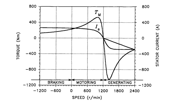
In Figures 2.18 through 2.20, the motor speed is limited to the 0 to rcsyn range, nsyn denoting the synchronous speed in r/min. This can be translated into the 1 to 0 range of slip. However, in general, an induction machine can operate with any value of slip, positive or negative. In Figure 2.21, the torque and stator current versus speed curves, such as those in Figure 2.18, are extended over the speed range from — nsyn to 2nsyn, so that the slip range is 2 to — 1. The negative magnitude, Is, of the stator current at supersynchronous speeds is meant to indicate that the phase shift of the current with respect to the stator voltage is greater than 90° and less than 270°. This implies a negative real power consumed by the motor, that is, the machine operates as a generator. Figure 2.21 illustrates three possible modes of operation of the induction motor: (1) braking, with s > 1 (i.e., n < 0); (2) motoring, with 0 < j < 1 (i.e., 0 < n < nsyn); and (3) generating, with s < 0 (i.e., n > nsyn).
In the braking mode,
the rotor is forced to rotate against the stator field, which causes high EMFs and currents induced in the rotor conductors. This mode can easily be imposed on a motor by reversing the field, which is accomplished by interchanging two leads between the power line and stator terminals, that is, by changing the phase sequence. However, the braking torque is low, so that this method of slowing the motor down is

FIGURE 2.21 Torque and current characteristics of the induction motor in a wide speed range.
not very effective. In addition, both the kinetic energy given up by the load and the electric energy supplied to the motor are dissipated in the rotor winding. Thus, no energy is recovered, and the motor is likely to overheat.
Much more efficient braking results from forcing the motor to operate in the generating mode,
which requires that the rotor turns faster than the field. This is done by reducing the field speed, nsyn, so that it revolves slower than the rotor. According to Eq. (2.4), it can be done by increasing the number, pp, of pole pairs of the stator or by decreasing the supply frequency, /. Indeed, certain motors have stator windings so arranged that they can be connected in more than one configuration, yielding, for instance, pp i = 1 and pp2 = 2. In the adjustable-speed drive systems, the motor is fed from an inverter, which supplies stator currents of variable frequency. There, the generating mode can easily be enforced by keeping track of the rotor speed and reducing the supply frequency accordingly.
