7.5
As subsequently demonstrated, stator and air-gap flux orientation systems require somewhat more complicated control algorithms than that for the rotor flux orientation described in the preceding sections. On the other hand, accurate estimation of the stator flux vector is easier than that of the rotor flux vector, while the air-gap flux vector, as mentioned in Section 7.3, can be measured directly.
Eq. (6.17) yields the condition for stator flux orientation as \QS = 0. Then, the developed torque is given by Eq. (7.4). Eq. (6.13) allows expressing the rotor current vector as
![tmp323-80_thumb[1] tmp323-80_thumb[1]](http://lh3.ggpht.com/_X6JnoL0U4BY/S1h4k6gn6OI/AAAAAAAAIWA/3nQAI3OKbGI/tmp32380_thumb1_thumb.png?imgmax=800)
![tmp323-81_thumb[1] tmp323-81_thumb[1]](http://lh3.ggpht.com/_X6JnoL0U4BY/S1h4nG2Sn5I/AAAAAAAAIWI/L1YXK_2JyJk/tmp32381_thumb1_thumb.png?imgmax=800)
Clearly, in a field-oriented motor, the \Ds component of the stator flux vector may not have the imaginary part implied by Eq. (7.24). Also, the magnitude, Xs= XDS, of this vector should be independent of the torque-producing component, /QS, of the stator current vector. Therefore, the reference signal, /gs, of the flux-producing current must be made dynamically dependent on the reference signal, /^s, of the torque-producing current in such a way that has no effect on \DS and that XDS is a real number.
Separation of Eq. (7.24) into the real and imaginary parts yields
![tmp323-82_thumb[1] tmp323-82_thumb[1]](http://lh4.ggpht.com/_X6JnoL0U4BY/S1h4pa92tsI/AAAAAAAAIWQ/2yBaAGWFSnI/tmp32382_thumb1_thumb.png?imgmax=800)
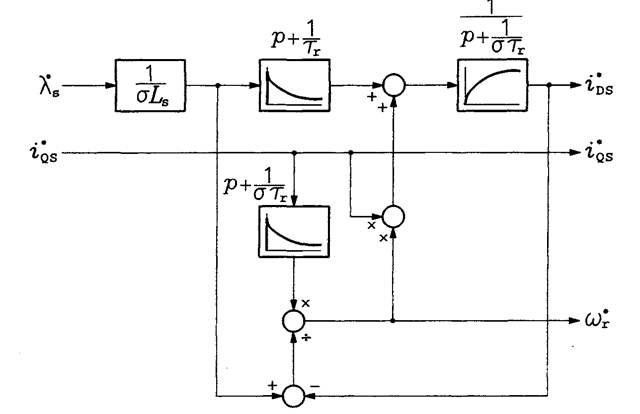
The system for dynamic decoupling of the flux-producing and torque-producing currents is shown in Figure 7.8.

FIGURE 7.8 System for dynamic decoupling of the flux-producing and torque-producing currents.
Clearly, in practical systems, the reference torque and flux values must be limited to avoid current overloads. Aside from that, in the classic rotor flux orientation schemes described in Sections 7.3 and 7.4, there are no additional limits on the torque and flux commands. However, such limits do exist in drives with the stator flux orientation and air-gap flux orientation. The steady-state value, o>*, of the rotor frequency command can be determined from Eqs. (7.27) and (7.28) by setting operator p to zero and eliminating /gs. As a result, the following quadratic equation is obtained:
![tmp323-84_thumb[1] tmp323-84_thumb[1]](http://lh6.ggpht.com/_X6JnoL0U4BY/S1h4vhX_4qI/AAAAAAAAIWg/3xcvnEg7Fn8/tmp32384_thumb1_thumb.png?imgmax=800)
It can be seen that it is the total leakage factor, cr, that imposes the “torque-per-flux-squared” limitation in the stator flux orientation schemes.
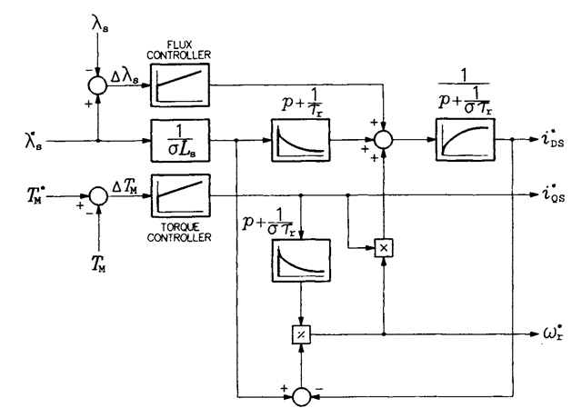
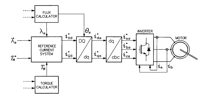
The decoupling system in Figure 7.8 can be augmented to a reference current system shown in Figure 7.9. The latter system forms an important part of the direct field orientation scheme shown in Figure 7.10. The stator flux vector is calculated from Eq. (6.15). Alternatively, it can be determined from information about the air-gap flux and stator current, as
![tmp323-85_thumb[1] tmp323-85_thumb[1]](http://lh6.ggpht.com/_X6JnoL0U4BY/S1h4w-TqHlI/AAAAAAAAIWo/YIYPSqVh7kQ/tmp32385_thumb1_thumb.png?imgmax=800)
![tmp323-86_thumb[1] tmp323-86_thumb[1]](http://lh4.ggpht.com/_X6JnoL0U4BY/S1h43j7ZVfI/AAAAAAAAIWw/SaFk4JH7REA/tmp32386_thumb1_thumb.png?imgmax=800)

FIGURE 7.9 Reference current system for the stator flux orientation scheme.

FIGURE 7.10 Block diagram of the ASD with stator flux orientation.
![tmp323-89_thumb[1] tmp323-89_thumb[1]](http://lh5.ggpht.com/_X6JnoL0U4BY/S1h5aMZcY9I/AAAAAAAAIXI/rxKxZgafPhc/tmp32389_thumb1_thumb.png?imgmax=800)
In today’s ASDs, control algorithms are implemented in digital systems, mostly microcontrollers and digital signal processors (DSPs). Changes from one type of field orientation to another are easy, as they are realized in the software only.
STATOR AND AIR-GAP FLUX ORIENTATION (Induction Motor)
Next post: DRIVES WITH CURRENT SOURCE INVERTERS (Induction Motor)
Previous post: INDIRECT FIELD ORIENTATION (Induction Motor)
