2.2
The three-phase stator winding produces a revolving magnetic field, which constitutes an important property of not only induction motors but also synchronous machines. Generation of the revolving magnetic field by stationary phase windings of the stator is explained in Figures 2.4 through 2.9. A simplified arrangement of the windings, each consisting of a one-loop single-wire coil, is depicted in Figure 2.4 (in real motors, several multiwire loops of each phase winding are placed in slots spread along the inner periphery of the stator). The coils are displaced in space by 120° from each other. They can be connected in wye or delta, which in
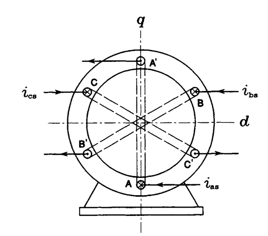
FIGURE 2.4 Two-pole stator of the induction motor.
this context is unimportant. Figure 2.5 shows waveforms of currents i^, ihs, and ics in individual phase windings. The stator currents are given by
![tmp2B7-24_thumb[1] tmp2B7-24_thumb[1]](http://lh6.ggpht.com/_X6JnoL0U4BY/S1hYVadkvSI/AAAAAAAAH7I/s0FaXjh2eGA/tmp2B724_thumb1_thumb.png?imgmax=800)
![tmp2B7-25_thumb[1] tmp2B7-25_thumb[1]](http://lh5.ggpht.com/_X6JnoL0U4BY/S1hYWmrWzAI/AAAAAAAAH7Q/9-Z4VOYn8L0/tmp2B725_thumb1_thumb.png?imgmax=800)

FIGURE 2.5 Waveforms of stator currents.
where /s p denotes their peak value and <o is the supply radian frequency; they are mutually displaced in phase by the same 120°. A phasor diagram of stator currents, at the instant of t = 0, is shown in Figure 2.6 with the corresponding distribution of currents in the stator winding. Current entering a given coil at the end designated by an unprimed letter, e.g., A, is considered positive and marked by a cross, while current leaving a coil at that end is marked by a dot and considered negative. Also shown are vectors of the magnetomotive forces (MMFs), J^a, «^b, and J^., produced by the phase currents. These, when added, yield the vector, J^, of the total MMF of the stator, whose magnitude is 1.5 times greater than that of the maximum value of phase MMFs. The two half-circular loops represent the pattern of the resultant magnetic field, that is, lines of the magnetic flux, d>s, of stator.
At t = 776, where T denotes the period of stator voltage, that is, a reciprocal of the supply frequency,/, the phasor diagram and distribution
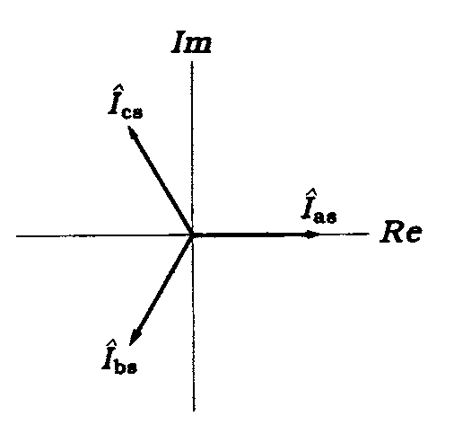
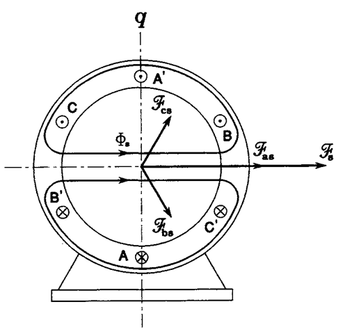
FIGURE 2.6 Phasor diagram of stator currents and the resultant magnetic field in a two-pole motor at att = 0.
of phase currents and MMFs are as seen in Figure 2.7. The voltage phasors have turned counterclockwise by 60°. Although phase MMFs did not change their directions, remaining perpendicular to the corresponding stator coils, the total MMF has turned by the same 60°. In other words, the spatial angular displacement, a, of the stator MMF equals the “electric angle,” orf. In general, production of a revolving field requires at least two phase windings displaced in space, with currents in these windings displaced in phase.
The stator in Figure 2.4 is called a two-pole stator because the magnetic field, which is generated by the total MMF and which closes through the iron of the stator and rotor, acquires the same shape as that produced by two revolving physical magnetic poles. A four-pole stator is shown in Figure 2.8 with the same values of phase currents as those in Figure 2.6. When, 776 seconds later, the phasor diagram has again turned by 60°, the pattern of crosses and dots marking currents in individual conductors of
![tmp2B7-29_thumb[2] tmp2B7-29_thumb[2]](http://lh5.ggpht.com/_X6JnoL0U4BY/S1hYlIRQ1II/AAAAAAAAH7w/iSWqtQRTn-A/tmp2B729_thumb2_thumb.png?imgmax=800)
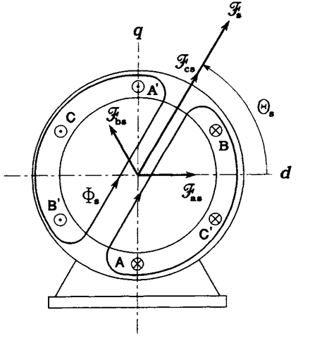
FIGURE 2.7 Phasor diagram of stator currents and the resultant magnetic field in a two-pole motor at <or = 60°.
![tmp2B7-31_thumb[1] tmp2B7-31_thumb[1]](http://lh3.ggpht.com/_X6JnoL0U4BY/S1hYrcoFVII/AAAAAAAAH8A/a6sUtRR8Xdg/tmp2B731_thumb1_thumb.png?imgmax=800)
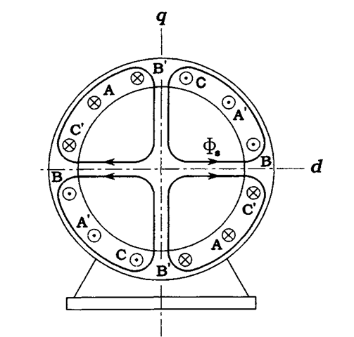
FIGURE 2.8 Phasor diagram of stator currents and the resultant magnetic field in a four-pole motor at lat = 0.
the stator has turned by 30° only, as seen in Figure 2.9. Clearly, the total MMF has turned by the same spacial angle, a, which is now equal to a half of the electric angle, o>t. The magnetic field is now as if it were generated by four magnetic poles, N-S-N-S, displaced by 90° from each other on the inner periphery of the stator. In general,
![tmp2B7-33_thumb[1] tmp2B7-33_thumb[1]](http://lh5.ggpht.com/_X6JnoL0U4BY/S1hYyTYXnUI/AAAAAAAAH8U/JQL2eynEWJg/tmp2B733_thumb1_thumb.png?imgmax=800)
where pp denotes the number of pole pairs. Dividing both sides of Eq. (2.2) by the angular velocity, o>syn, of the field, called a synchronous velocity, is obtained as
![tmp2B7-34_thumb[1] tmp2B7-34_thumb[1]](http://lh5.ggpht.com/_X6JnoL0U4BY/S1hYzgZm1uI/AAAAAAAAH8c/cJmZwOye0bQ/tmp2B734_thumb1_thumb.png?imgmax=800)
![tmp2B7-35_thumb[3] tmp2B7-35_thumb[3]](http://lh5.ggpht.com/_X6JnoL0U4BY/S1hY02_JPRI/AAAAAAAAH8k/ai1Hfsi1qWo/tmp2B735_thumb3_thumb.png?imgmax=800)
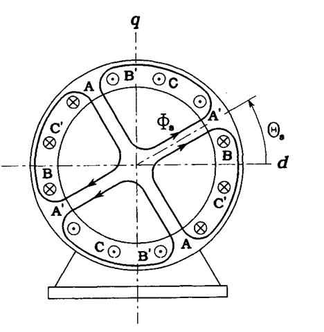
FIGURE 2.9 Phasor diagram of stator currents and the resultant magnetic field in a four-pole motor at <of = 60°.
while the synchronous speed, nsyn, of the field in revolutions per minute (r/min) is
![tmp2B7-37_thumb[1] tmp2B7-37_thumb[1]](http://lh5.ggpht.com/_X6JnoL0U4BY/S1hY4pZGHkI/AAAAAAAAH80/a5rKQJBVfOo/tmp2B737_thumb1_thumb.png?imgmax=800)
To explain how a torque is developed in the rotor, consider an arrangement depicted in Figure 2.10 and representing an “unfolded” motor. Conductor CND, a part of the squirrel-cage rotor winding, moves leftward with the speed ux. The conductor is immersed in a magnetic field produced by stator winding and moving leftward with the speed u2, which is greater than Kj. The field is marked by small crossed circles representing lines of magnetic flux, <j>, directed toward the page. Thus, with respect to the field, the conductor moves to the right with the speed This motion induces (hence the name of the motor) an electromotive force (EMF), e, whose polarity is determined by the well-known right-hand
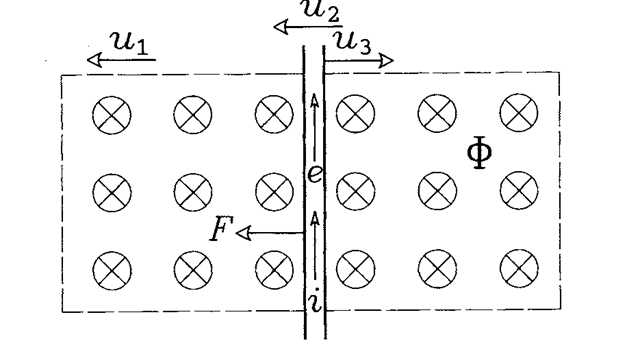
FIGURE 2.10 Generation of electrodynamic force in a rotor bar of the induction motor.
rule. Clearly, no EMF would be induced if the speed of the conductor (i.e., that of the rotor) and speed of the field were equal, because according to Faraday’s law the EMF is proportional to the rate of change of flux linkage of the conductor. If the conductor was stationary with respect to the field, that is, if the rotor rotated with the synchronous speed, no changes would be experienced in the flux linking the conductor.
The EMF, e, produces a current, i, in the conductor. The interaction of the current and magnetic field results in an electrodynamic force, F, generated in the conductor. The left-hand rule determines direction of the force. It is seen that the force acts on the conductor in the same direction as that of the field motion. In other words, the stator field pulls conductors of the rotor, which, however, move with a lower speed than that of the field. The developed torque, TM, is a product of the rotor radius and sum of electrodynamic forces generated in individual rotor conductors.
When an induction machine operates as a motor, the rotor speed, wM, is less than the synchronous velocity, wsyn. The difference of these velocities, given by
![tmp2B7-39_thumb[2] tmp2B7-39_thumb[2]](http://lh3.ggpht.com/_X6JnoL0U4BY/S1hY72WLgFI/AAAAAAAAH9I/y37eue8H-v0/tmp2B739_thumb2_thumb.png?imgmax=800)
and called a slip velocity, is positive. Dividing the slip velocity by oosyn yields the so-called slip, s, of the motor, defined as
![tmp2B7-40_thumb[3] tmp2B7-40_thumb[3]](http://lh3.ggpht.com/_X6JnoL0U4BY/S1hY9D16GXI/AAAAAAAAH9Q/fR7TVNBtrec/tmp2B740_thumb3_thumb.png?imgmax=800)
Here, the slip is positive. However, if the machine is to operate as a generator, in which the developed torque opposes the rotor motion, the slip must be negative, meaning that the rotor must move faster than the field.
REVOLVING MAGNETIC FIELD (Induction Motor)
Next post: STEADY-STATE EQUIVALENT CIRCUIT (Induction Motor)
Previous post: CONSTRUCTION (Induction Motor)
