1.4
The concept of operating quadrants plays an important role in the theory and practice of electric drives. Both the torque, TM, developed in a motor and speed, a>M, of the rotor can assume two polarities. For instance, watching the motor from the front end, positive polarity can be assigned to the clockwise direction and negative polarity to the counterclockwise direction. Because the output (mechanical) power, Pout, of a motor is given by
![tmp2B7-18_thumb[1] tmp2B7-18_thumb[1]](http://lh5.ggpht.com/_X6JnoL0U4BY/S1hWNd2_kBI/AAAAAAAAH6Y/sp9b1lfVAHY/tmp2B718_thumb1_thumb.png?imgmax=800)
the torque and speed polarities determine the direction of flow of power between the motor and load. With Pout > 0, the motor draws electric power from a supply system and converts it into mechanical power delivered to the load. Conversely, Pout < 0 indicates a reversed power flow, with the motor being driven by the load that acts as a prime mover. If proper arrangements are made, the motor can then operate as a generator and deliver electric power to the supply system. Such a regenerative mode of operation can be employed for braking a high-inertia load or lowering a load in a lift drive, reducing the net energy consumption by the motor.
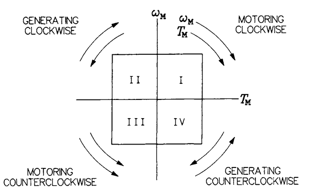
The operating quadrants in the already mentioned ((oM,rM) plane correspond to the four possible combinations of polarities of torque and speed, as shown in Figure 1.4. The power flow in the first quadrant and third quadrant is positive, and it is negative in the second and fourth quadrants. To illustrate the idea of operating quadrants, let us consider two drive systems, that of an elevator and that of an electric locomotive. When lifting, the torque and speed of elevator’s motor have the same

FIGURE 1.4 Operating quadrants in the (a)M,rM) plane.
polarity. However, when lowering, the motor rotates in the other direction while the polarity of the torque remains unchanged. Indeed, in both cases the motor torque must counterbalance the unidirectional gravity torque. Thus, assuming a positive motor speed when lifting, the motor is seen to operate in the first quadrant, while operation in the fourth quadrant occurs when lowering. In the latter situation, it is the weight of the elevator cage that drives the motor, and the potential energy of the cage is converted into electrical energy in the motor. The supply system of the motor must be so designed that this energy is safely dissipated or returned to the power source.
As for the locomotive,
both polarities of the motor speed are possible, depending on the direction of linear motion of the vehicle. Also, the motor torque can assume two polarities, agreeing with the speed when the locomotive is in the driving mode and opposing the speed when braking. The enormous kinetic energy would strain the mechanical brakes if they were the only source of braking torque. Therefore, all electric locomotives (and other electric vehicles as well) have a provision allowing electrical braking, which is performed by forcing the motor to operate as a generator. It can be seen that the two possible polarities of both the torque and speed make up for four quadrants of operation of the drive. For example, first quadrant may correspond to the forward driving, second quadrant to the forward braking, third quadrant to the backward driving, and fourth quadrant to the backward braking. Yet, it is worth mentioning that, apart from electric vehicles, the four-quadrant operation is not very common in practice. Most of the ASDs, as well as uncontrolled motors, operate in the first quadrant only.
Power electronic converters feeding induction motors in ASDs also can operate in up to four quadrants in the current-voltage plane. As known from the theory of electric machines, the developed torque and the armature current are closely related. The same applies to the speed and armature voltage of a machine. Therefore, if a converter-fed motor operates in a certain quadrant, the converter operates in the same quadrant.
