5.2
Analysis of Eq. (5.12) leads to the following conclusions:
1. If cor = 1/tp then the maximum (pull-out) torque, rMmax, is developed in the motor. It is given by
![tmp323-11_thumb[1] tmp323-11_thumb[1]](http://lh4.ggpht.com/_X6JnoL0U4BY/S1hujaWO84I/AAAAAAAAINQ/6mh_rDDLIA8/tmp32311_thumb1_thumb.png?imgmax=800)
and the corresponding critical slip, sCI, is
![tmp323-12_thumb[1] tmp323-12_thumb[1]](http://lh5.ggpht.com/_X6JnoL0U4BY/S1hukfSXo7I/AAAAAAAAINY/XXLnm4a5hM8/tmp32312_thumb1_thumb.png?imgmax=800)
2. Typically, induction motors operate well below the critical slip, so that cor < 1/tf. Then, (tra>r)2 + 1 <=» 1, and the torque is practically proportional to (or For a stiff mechanical characteristic
of the motor, possibly high flux and low rotor resistance are required.
3. When the stator flux is kept constant, the developed torque is independent of the supply frequency, /. On the other hand, the speed of the motor strongly depends on / [see Eq. (3.3)].
It must be stressed that Eq. (5.12) is only valid when the stator flux is kept constant, independently of the slip. In practice, it is usually the stator voltage that is constant, at least when the supply frequency does not change. Then, the stator flux does depend on slip, and the critical slip is different from that given by Eq. (5.23). Generally, for a given supply frequency, the mechanical characteristic of an induction motor strongly depends on which motor variable is kept constant.
Thus, to maintain the flux at a constant, typically rated level, the stator voltage should be adjusted in proportion to the supply frequency. This is the simplest approach to the speed control of induction motors, referred to as Constant Volts/Hertz (CVH) method. It can be seen that no feedback is inherently required, although in most practical systems the stator current is measured, and provisions are made to avoid overloads.
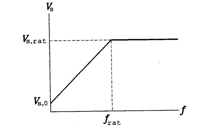
For the low-speed operation, the voltage drop across the stator resistance must be taken into account in maintaining constant flux, and the stator voltage must be appropriately boosted. Conversely, at speeds exceeding that corresponding to the rated frequency,/rat, the CVH condition cannot be satisfied because it would mean an overvoltage. Therefore, the stator voltage is adjusted in accordance to the following rule:
![tmp323-13_thumb[1] tmp323-13_thumb[1]](http://lh6.ggpht.com/_X6JnoL0U4BY/S1hulic76yI/AAAAAAAAINg/u4XWdoHJYKE/tmp32313_thumb1_thumb.png?imgmax=800)
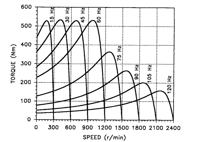
where Vs 0 denotes the rms value of the stator voltage at zero frequency. Relation (5.25) is illustrated in Figure 5.3. For the example motor, Vs0 = 40 V. With the stator voltage so controlled, its mechanical characteristics for various values of the supply frequency are depicted in Figure 5.4.
Frequencies higher than the rated (base) frequency result in reduction of the developed torque. This is caused by the reduced magnetizing current, that is, a weakened magnetic field in the motor. Accordingly, the motor is said to operate in the field weakening mode. The region to the right from the rated frequency is often called the constant power area, as distinguished from the constant torque area to the left from the said frequency. Indeed, with the torque decreasing when the motor speed increases, the product of these two variables remains constant. Note that the described characteristics of the motor can easily be explained by the

FIGURE 5.3 Voltage versus frequency relation in the CVH drives.

FIGURE 5.4 Mechanical characteristics of the example motor with the CVH control.
impossibility of sustained operation of an electric machine with the output power higher than rated.
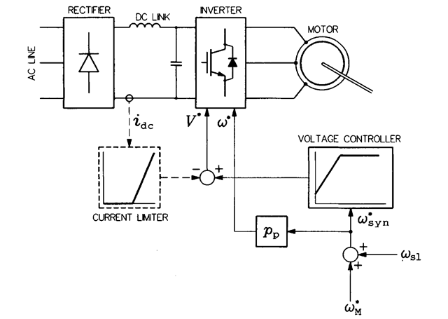
A simple version of the CVH drive is shown in Figure 5.5. A fixed value of slip velocity, a)s], corresponding to, for instance, 50% of the rated torque, is added to the reference velocity, (ofo, of the motor to result in the reference synchronous frequency, a)*yn. This frequency is next multiplied by the number of pole pairs, pp, to obtain the reference output frequency, w*, of the inverter, and it is also used as the input signal to a voltage controller. The controller generates the reference signal, V*, of the inverter’s fundamental output voltage. Optionally, a current limiter can be employed to reduce the output voltage of the inverter when too high a motor current is detected. The current, idc, measured in the dc link is a dc current, more convenient as a feedback signal than the actual ac motor current.
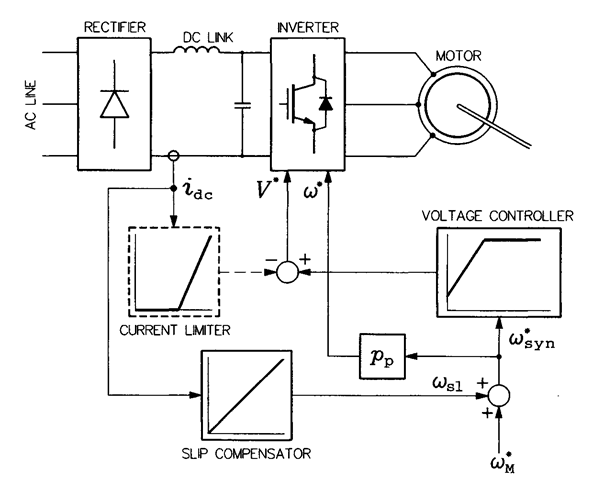
Clearly, highly accurate speed control is not possible, because the actual slip varies with the load of the motor. Yet, in many practical applications, such as pumps, fans, mixers, or grinders, high control accuracy is unnecessary. The basic CVH scheme in Figure 5.5 can be improved by adding slip compensation based on the measured dc-link current. The o)s, signal is generated in the slip compensator as a variable proportional to idc. A so modified drive system is shown in Figure 5.6.

FIGURE 5.5 Basic CVH drive system.

FIGURE 5.6 CVH drive system with slip compensation.
OPEN-LOOP SCALAR SPEED CONTROL (CONSTANT VOLTS/HERTZ) (Induction Motor)
Next post: CLOSED-LOOP SCALAR SPEED CONTROL (Induction Motor)
Previous post: TWO-INDUCTANCE EQUIVALENT CIRCUITS OF THE INDUCTION MOTOR
