2.6
It has been said that an induction machine rotating with the speed higher than that of the magnetic field of the stator operates as a generator, feeding electrical power back to the supply system. This property is utilized in, for example, induction generators driven by a wind turbine and connected to the grid. The question is whether an induction machine can operate as
a stand-alone generator of electric energy. Basically, the answer is negative, because in the absence of magnetic field no EMF can be induced in the rotor.
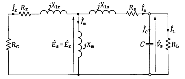
Yet, stand-alone induction generators are feasible, because to maintain the magnetic field only the reactive power is required. Capacitors connected between the stator terminals of an induction machine can serve as such a source. When the machine is driven by a prime mover, a field buildup is initiated by the residual flux density in stator iron. Analysis of such an induction generator is based on the per-phase equivalent circuit shown in Figure 2.22. The negative resistance RG represents a source of the input mechanical power, Pin. This resistance is a counterpart of the equivalent load resistance, Z?L, in Figure 2.15 and given by the same relation, that is,
![tmp2B7-76_thumb[1] tmp2B7-76_thumb[1]](http://lh6.ggpht.com/_X6JnoL0U4BY/S1hbtudbawI/AAAAAAAAIBs/PW6xt1Iz71Q/tmp2B776_thumb1_thumb.png?imgmax=800)
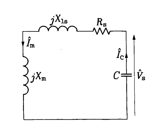
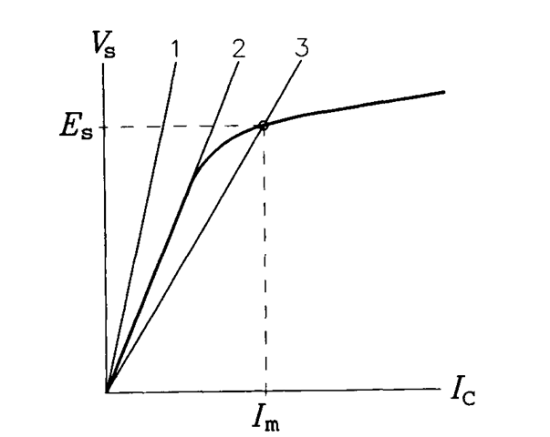
For analysis purposes, magnetic saturation of iron of the machine must be taken into account when expressing the stator EMF, Es, in terms of the magnetizing current, Im. This can be explained by considering the no-load operation of the generator. No real power is supplied by the rotor, which allows removing the rotor part from the equivalent curcuit in Figure 2.22, yielding the circuit in Figure 2.23. Neglecting the small voltage drop across the stator resistance and leakage reactance, the operating point can be found at the intersection of the magnetization curve, Es = J{Im), and the capacitor load line, Vs = XCIC, where Xc denotes the capacitor impedance, l/(o)C), and Ic is the capacitor current. As illustrated in Figure 2.24, a too-small capacitance (line 1) is insufficient to provide excitation for the generator, while no solution can be found if the capacitor load

FIGURE 2.22 Per-phase equivalent circuit of the stand-alone induction generator.

FIGURE 2.23 Per-phase equivalent circuit of the stand-alone induction generator on no load.

FIGURE 2.24 Determination of the operating point of the induction generator.
line (line 2) coincides with the straight portion of the magnetization curve. On the other hand, a properly selected capacitance (line 3) should not be too large, to avoid unnecessarily high magnetizing and capacitor currents.
It must be stressed that C denotes a per-phase capacitance. In practice, the capacitors are connected between each pair of output terminals, that is, they are subjected to the line-to-line voltages. Analyzing the total amount of reactive power associated with these capacitors, it can easily be found that the per-phase capacitance, C, equals the actual capacitance, Cact, of the single capacitor only when stator windings are connected in delta (which is the predominant practical connection). With stator windings connected in wye, C = 3Cact.
The following set of equations can be used for a computer-based analysis of the induction generator operating with the output frequency
co. A purely resistive load, /?L, is assumed. The load, capacitor, and stator currents, IL, Ic, and 7S, respectively, are determined as
![tmp2B7-80_thumb[1] tmp2B7-80_thumb[1]](http://lh5.ggpht.com/_X6JnoL0U4BY/S1hcMuA2pzI/AAAAAAAAICM/8herBURRxOU/tmp2B780_thumb1_thumb.png?imgmax=800)
![tmp2B7-81_thumb[1] tmp2B7-81_thumb[1]](http://lh6.ggpht.com/_X6JnoL0U4BY/S1hcPt0Hj0I/AAAAAAAAICU/1itbD8F_wH0/tmp2B781_thumb1_thumb.png?imgmax=800)
![tmp2B7-82_thumb[1] tmp2B7-82_thumb[1]](http://lh6.ggpht.com/_X6JnoL0U4BY/S1hcQ3hiwNI/AAAAAAAAICc/EBD7gSEk7aE/tmp2B782_thumb1_thumb.png?imgmax=800)
Residual magnetism in the iron of a stand-alone induction generator is necessary for the avalanche buildup of the magnetic field when the machine starts turning. The output voltage strongly depends on the load, especially on the reactive component of the load impedance. The slip and, consequently, the output frequency also are load dependent, albeit to a much lesser degree. Usually, the voltage of induction generators is conditioned using power electronic converters.
INDUCTION GENERATOR (Induction Motor)
Next post: SUMMARY (Induction Motor)
Previous post: STEADY-STATE CHARACTERISTICS (Induction Motor)
