8.3
The Direct Self-Control (DSC) method, proposed by Depenbrock in 1985, is intended mainly for high-power ASDs with voltage source inverters. Typically, slow switches, such as GTOs, are employed in such inverters, and low switching frequencies are required. Therefore, in DSC drives, the inverter is made to operate in a mode similar to the square-wave one, with occasional zero states thrown in. The zero states disappear when the
drive runs with the speed higher than rated, that is, in the field weakening area, where, as in all other ASDs, the inverter operates in the square-wave mode.
DSC ASDs are often misrepresented as a subclass of DTC drives.
However, the principle of DSC is different from that of DTC. To explain this principle, note that while the output voltage waveforms in voltage source inverters are discontinuous, the time integrals of these waveforms are continuous and, in a piece wise manner, they approach sine waves. It can be shown that using these integrals, commonly called virtual fluxes, and hysteresis relays in a feedback arrangement, the square-wave operation of the inverter may be enforced with no external signals (hence the “self” term in the name of the method). The output frequency, fa, of the so-operated inverter is proportional to the V/X* ratio, where V{ denotes the dc input voltage of the inverter and X* is the reference magnitude of the virtual flux. Specifically,
![tmp362-3_thumb[1] tmp362-3_thumb[1]](http://lh6.ggpht.com/_X6JnoL0U4BY/S1iB43XGTRI/AAAAAAAAIZw/zMmsn_4al3o/tmp3623_thumb1_thumb.png?imgmax=800)
when the virtual fluxes are calculated as time integrals of the line-to-line output voltages of the inverter, and
![tmp362-4_thumb[1] tmp362-4_thumb[1]](http://lh5.ggpht.com/_X6JnoL0U4BY/S1iB6BcYTQI/AAAAAAAAIZ4/89Vm-TQaWnM/tmp3624_thumb1_thumb.png?imgmax=800)
when the line-to-neutral voltages are integrated. The self-control scheme is illustrated in Figure 8.13 and characteristics of the hysteresis relays are shown in Figure 8.14. Waveforms of the virtual fluxes are depicted in Figure 8.15 (notice the negative phase sequence). As shown in Figure
8.16, the trajectories of the corresponding flux vectors, \, are hexagonal, both for the line-to-neutral and line-to-line voltage integrals. As in the case of motor variables, the magnitude, X, of the flux vector is 1.5 times greater than the amplitude of flux waveforms.
In spite of the hexagonal trajectory and nonsinusoidal waveforms of virtual fluxes, the total harmonic distortion of these waveforms is low. It can further be reduced by the so-called corner folding, illustrated in Figure
8.17. The flux trajectory becomes closer to a circle, albeit at the expense of a somewhat more complicated self-control scheme and a threefold increase in the switching frequency.
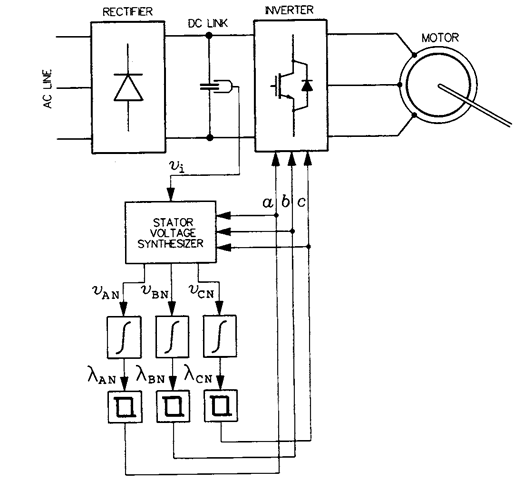
FIGURE 8.13 Inverter self-control scheme.
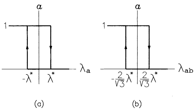
FIGURE 8.14 Characteristics of the hysteresis relays in the inverter self-contrc scheme: (a) line-to-neutral voltages integrated, (b) line-to-line voltages integrated.
The total harmonic distortion, THD, of the waveform in question is defined as the ratio of the harmonic content, Ah, of this waveform to the fundamental flux, Al. The harmonic content can be determined as a geometrical difference (square root of a difference of squares) of the rms value, A, and the fundamental, Ax.
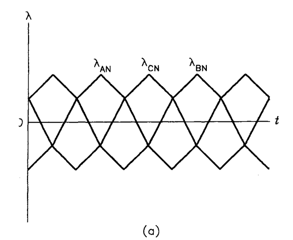
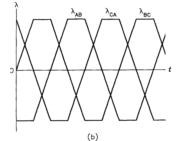
FIGURE 8.15 Waveforms of virtual fluxes: (a) line-to-neutral voltage integrals, (b) line-to-line voltage integrals.
The virtual flux waveform has the odd symmetry and half-wave symmetry. Therefore, it is sufficient to consider a half of it, from 0° to 180°. Denoting the peak value of the waveform by Amax, the expression for the waveform is
![tmp362-9_thumb[1] tmp362-9_thumb[1]](http://lh5.ggpht.com/_X6JnoL0U4BY/S1iC86Vlq_I/AAAAAAAAIag/wKUEHG4lzfc/tmp3629_thumb1_thumb.png?imgmax=800)
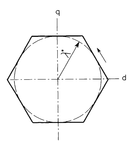
FIGURE 8.16 Hexagonal trajectory of the virtual flux vector.
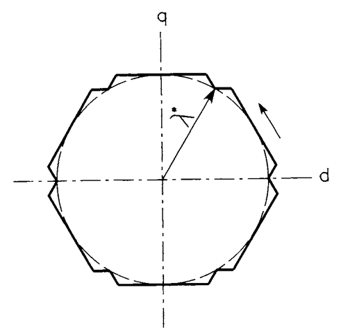
FIGURE 8.17 Trajectory of the virtual flux vector with “corner folding.”
![tmp362-12_thumb[1] tmp362-12_thumb[1]](http://lh4.ggpht.com/_X6JnoL0U4BY/S1iDGEIDS8I/AAAAAAAAIa4/e7a_ixY8i2Y/tmp36212_thumb1_thumb.png?imgmax=800)
![tmp362-13_thumb[1] tmp362-13_thumb[1]](http://lh3.ggpht.com/_X6JnoL0U4BY/S1iEzikMRGI/AAAAAAAAIbA/wczOIm-EKZk/tmp36213_thumb1_thumb.png?imgmax=800)
![tmp362-14_thumb[1] tmp362-14_thumb[1]](http://lh5.ggpht.com/_X6JnoL0U4BY/S1iFtbmvDII/AAAAAAAAIbI/0u_ZTRVghjU/tmp36214_thumb1_thumb.png?imgmax=800)
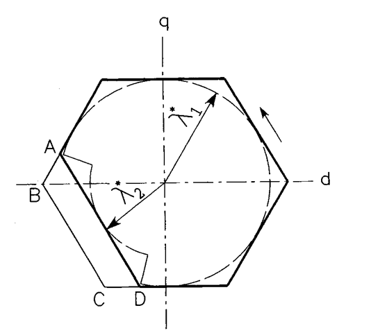
FIGURE 8.18 Acceleration of the virtual flux vector by reduction of the reference magnitude of the vector.
![tmp362-16_thumb[1] tmp362-16_thumb[1]](http://lh6.ggpht.com/_X6JnoL0U4BY/S1iFzjJ3peI/AAAAAAAAIbY/01UElCLkbWg/tmp36216_thumb1_thumb.png?imgmax=800)
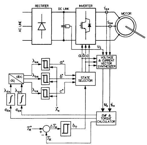
FIGURE 8.19 Block diagram of the DSC drive system.
are forwarded to a state selector. The selector generates switching signals, a, b, and c, which, if expressing active states of the inverter, equal their respective reference values. However, if a zero state is needed, the selector chooses State 0 or State 7, based on the previous state of the inverter, so that switches in only one inverter phase are activated. In more advanced versions of the DSC schemes, the features of corner folding and trajectory deformation and other enhancements are employed.
