GPS has been available for civil and military use for more than two decades. That period of time has witnessed the creation of numerous new GPS applications. Because it provides high-accuracy positioning in a cost-effective manner, GPS has found its way into many industrial applications, replacing conventional methods in most cases. For example, with GPS, machineries can be automatically guided and controlled. This is especially useful in hazardous areas, where human lives are endangered. Even some species of birds are benefiting from GPS technology, as they are being monitored with GPS during their immigration season. This way, help can be presented as needed. This topic describes how GPS is being used in land, marine, and airborne applications.
GPS for the utilities industry
Accurate and up-to-date maps of utilities are essential for utility companies. The availability of such maps helps electric, gas, and water utility companies to plan, build, and maintain their assets.
The GPS/GIS system provides a cost-effective, efficient, and accurate tool for creating utility maps. With the help of GPS, locations of features such as gas lines can be accurately collected, along with their attributes (such as their conditions and whether or not a repair is needed). The collected information can then be used by a GIS system to create updated utility maps.
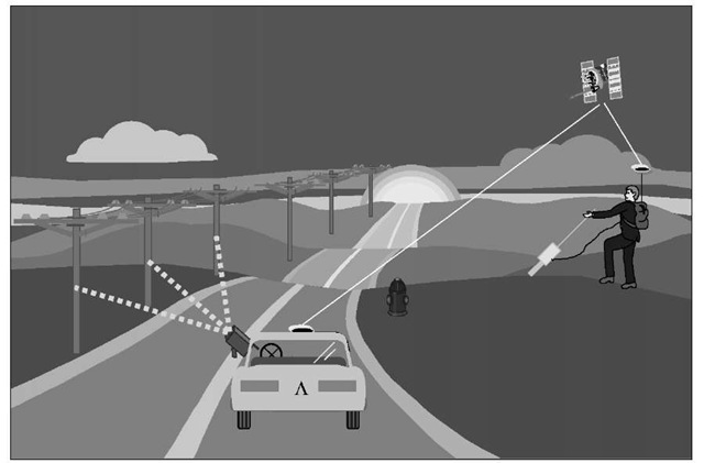
In situations of poor GPS reception, such as in urban canyons, it might be useful to use integrated GPS and LRF systems [1]. This integrated system is an efficient tool for rapid utility mapping. A GPS receiver remains in the open for the best signal reception, while the LRF measures the offset information (range and azimuth) to the utility assets such as light poles (see Figure 10.1). The processing software should be able to combine both the GPS and the LRF information.
Buried utilities such as electric cables or water pipes can also be mapped efficiently using GPS (Figure 10.1). With the help of a pipe/cable locator attached to the second port of the GPS handheld controller, accurate information on the location and the depth of the buried utility can be collected. This is a very cost-effective and efficient tool, as no ground marking is required.
Figure 10.1 GPS for utility mapping.
GPS for forestry and natural resources
GPS has been applied successfully in many areas of the forest industry. Typical applications include fire prevention and control, harvesting operations, insect infestation, boundary determination, and aerial spraying [2].
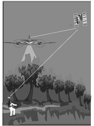
With thousands of fires facing the forest services every year, an efficient resource-management system is essential. GPS is a key technology that enables the system operator to identify and monitor the exact location of the resources (Figure 10.2). With the help of GIS and a good communication system, appropriate decisions can be made.
In the past, aerial photography was the only means of providing information on the shape and location of cut blocks before completing harvesting operations. Such information was often lacking accuracy. With the use of differential GPS, however, this information can be accurately determined in real time.
Figure 10.2 GPS applications in forestry.
GPS has also been a very useful tool for wildlife management and insect infestation. Using its precise positioning capability, GPS can determine the locations of activity centers. These locations can be easily accessed using GPS waypoint navigation (see Section 10.15).
GPS surveying is becoming the preferred method for forest boundaries determination. With real-time GPS, up to 75% time and cost reductions can be obtained.Other integrated systems, including GPS/digital barometers and GPS/laser digital videography, have been applied successfully in the forest industry as well.
GPS for precision farming
The ability of DGPS to provide real-time submeter- or even decimeter-level accuracy has revolutionized the agricultural industry [3, 4]. GPS applications in precision farming include soil sample collection, chemical applications control, and harvest yield monitors (Figure 10.3).
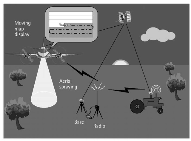
Figure 10.3 GPS for precision farming.
When collecting soil samples, GPS is used to precisely locate the sample points from a predefined grid (Figure 10.3). After testing the soil samples, information such as nitrogen and organic material contents can be obtained. This type of information is mapped and used as a reference to guide farmers in efficiently and economically treating soil problems.
When GPS is integrated with an aerial guidance system, the field sprayer can be guided through a moving map display. Based on the sprayer’s location, the system will apply the chemicals at the right spots, with minimal overlap, and automatically adjust their rate. This, in addition to increasing productivity, ensures that chemicals and fuel are used efficiently.
GPS is also used to map crop yields. As the DGPS-equipped harvester moves across the field, yield rates are recorded along with DGPS-derived positions. This information is then mapped to show the yield rate.
Easy-to-use integrated systems with only a few buttons are now available on the market. DGPS corrections are available from the government-operated DGPS/beacon service free of charge, as well as from a number of commercial services. The user’s own base station may be built as well (Figure 10.3).
GPS for civil engineering applications
Civil engineering works are often done in a complex and unfriendly environment, making it difficult for personnel to operate efficiently. The ability of GPS to provide real-time submeter- and centimeter-level accuracy in a cost-effective manner has significantly changed the civil engineering industry. Construction firms are using GPS in many applications such as road construction, Earth moving, and fleet management.
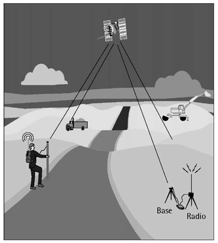
In road construction and Earth moving, GPS, combined with wireless communication and computer systems, is installed onboard the Earth-moving machine [5]. Designed surface information, in a digital format, is uploaded into the system. With the help of the computer display and the real-time GPS position information, the operator can view whether the correct grade has been reached (see Figure 10.4). In situations in which millimeter-level elevation is needed, GPS can be integrated with rotated beam lasers [6].
Figure 10.4 GPS for construction applications.
The same technology (i.e., combined GPS, wireless communications, and computers) is also used for foundation works (e.g., pile positioning) and precise structural placement (e.g., prefabricated bridge sections and coastal structures). In these applications, the operators are guided through the onboard computer displays, eliminating the need for conventional methods [7].
GPS is also used to track the location and usage of equipment at different sites. By sending this information to a central location, GPS enables contractors to deploy their equipment more efficiently. Moreover, vehicle operators can be efficiently guided to their destinations.
GPS for monitoring structural deformations
Since its early development, GPS has been used successfully in monitoring the stability of structures, an application that requires the highest possible accuracy. Typical examples include monitoring the deformation of dams, bridges, and TV towers. Monitoring ground subsidence of oil fields and mining areas are other examples where GPS has been used successfully. In some cases, GPS may be supplemented by other systems such as INS or total stations to work more efficiently. Deformation monitoring is done by taking GPS measurements over the same area at different time intervals [7].
Slow-deforming structures such as dams require submillimeter- to millimeter-level accuracy to monitor their displacement. Although this accuracy level may be achieved with GPS alone under certain conditions, it is not a cost-effective method [7]. To effectively monitor such structures, GPS should be supplemented with geotechnical sensors and special types of total stations.
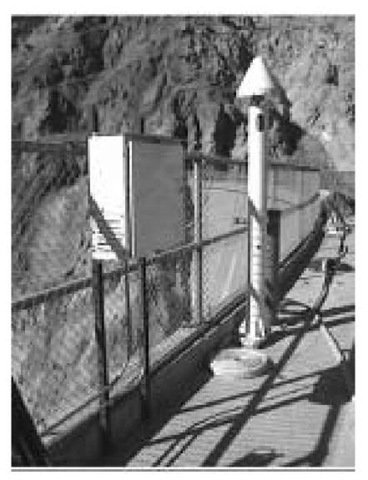
Bridges, in contrast, are subjected to vibrations caused by dynamic traffic loads. To effectively monitor such cyclic deforming structures, dual GPS receivers should be located at several points with maximum amplitude of cyclic deformation [7]. For example, in monitoring the world’s longest suspension bridge (Akashi Bridge, Japan), a GPS receiver is installed at the midpoint of the bridge while two others are installed at the main towers. Figure 10.5 shows another example in which the Ashtech Z12 dual-frequency receiver is used for monitoring bridge deformation. As the GPS data collection rate is currently limited to 10 Hz, an INS system may supplement the GPS system, in some cases, to monitor the high-frequency portion of the structure vibration.
GPS for open-pit mining
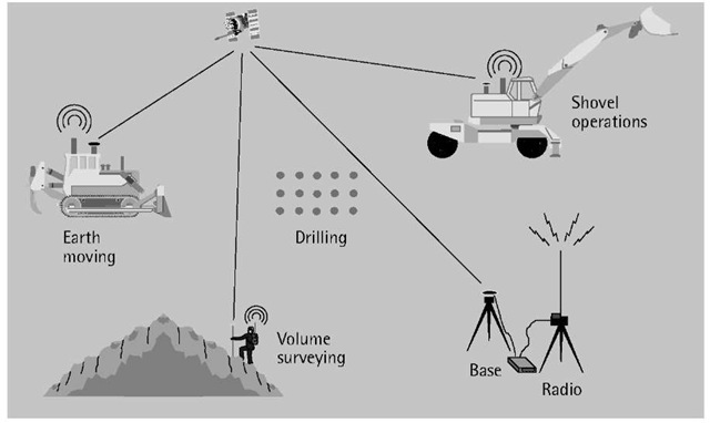
Until recently, conventional surveying was the only method available for staking drill patterns and other mining surveying. As a result of the harsh mining environment, however, stakes were often buried or displaced. In addition, drill operators had no precise way of determining the actual bit depth. Likewise, there was no way of monitoring the drill performance in the various geological layers or monitoring the haul trucks in an efficient way. More recently, however, the development of modern positioning systems and techniques, particularly RTK GPS, has dramatically improved various mining operations [8, 9]. In open-pit mines, for example, the use of RTK GPS has significantly improved several mining operations such as drilling, shoveling, vehicle tracking, and surveying. RTK GPS provides centimeter-level positioning accuracy, and requires only one base receiver to support any number of rovers.
Figure 10.5 GPS for monitoring bridge deformation.
As the pit deepens, part of the GPS signal may be blocked by the steep walls of the mine, causing a positioning problem. However, this problem, has been successfully overcome by integrating GPS with other positioning systems, mainly the pseudolite system (see Section 9.5) [10].
The mining cycle includes several phases, with ore excavation being one of the most important [11]. Excavating the ore is done by drilling a predefined pattern of blast holes, which are then loaded with explosive charges. The pattern of blast holes is designed in such a way that the size of the rock fragmentation is optimized. As such, it is important that the drills be precisely positioned over the blast holes, or otherwise redrilling may be required. An efficient way of guiding the drills is through integrating GPS with a drill navigation and monitoring system consisting of an onboard computer and drilling software. Some systems utilize two GPS receivers, mounted on the top of the drill mast, for precise real-time position and orientation of the drill. The designed drill patterns are sent to the onboard computer via radio link, and are then used by the integrated system to guide the drill operator to precisely position the drill over blast holes (see Figure 10.6). This is done automatically without staking out. In addition, the onboard computer displays other information such as the location and depth of each drill hole. This is very important as it allows the operator to view whether or not the target depth has been reached. As well, the system accumulates information on the rock hardness and the drill productivity, which can be sent to the engineering office in near real time via radio link. Such information can be used not only in monitoring the drill productivity from the engineering office, but also in understanding the rock properties, which enables better future planning [11].
GPS is also used for centimeter-level-accuracy guidance of shoveling operations (Figure 10.6). Shovels are used in loading the ore into the haul trucks, which then transport it and unload it in stockpiles. With an integrated GPS and shovel guidance and monitoring system, elevation control can be automated. With the help of the system display, shovel operators are able to keep the correct grade. This is done automatically without the need for grade control by conventional surveying methods. Similar to the drilling, shoveling productivity can be sent to the engineering office in near real time via radio link for monitoring and analysis.
Figure 10.6 GPS use in open-pit mining.
In transporting the ore, haul trucks use continuously changing mining roads and ramps. Unless efficiently routed, safety and traffic problems would be expected, which cause an increase in the truck cycle time. The use of GPS, wireless communication, and a computer system onboard the haul trucks solve this problem efficiently. With the help of a computerized dispatch system, haul trucks can be guided to their destination using the best routes. In addition, the dispatch center can collect information on the status of each haul truck as well as the traffic conditions. Analyzing the traffic conditions is particularly important in devising a more appropriate road design [11].
GPS is also used in other phases of the mining cycle, for example, in checking the coordinates of the individual points and volume surveying. Either the RTK or the non-RTK GPS could be used for these functions (Figure 10.6).
