This section presents methods for transforming points and vectors between rectangular coordinate systems. The axes of each coordinate system are assumed to be right-handed and orthogonal. Three dimensions are used throughout the discussion; however, the discussion is equally valid for![]()
The Direction Cosine Matrix
Let![]() represent a right-handed orthogonal coordinate system. Let
represent a right-handed orthogonal coordinate system. Let![]() be a vector from the origin
be a vector from the origin![]() of the
of the![]() frame to the point P. The representation of the vector
frame to the point P. The representation of the vector![]() with respect to frame
with respect to frame![]() is
is
axes and where
are unit vectors along the ![]() axes and
axes and
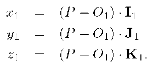
The vector![]() contains the coordinates of the point P with respect to the axes of
contains the coordinates of the point P with respect to the axes of![]() and is the representation of the vector
and is the representation of the vector![]() with respect to
with respect to![]() The physical interpretations of the coordinates is that they are the projections of the vector
The physical interpretations of the coordinates is that they are the projections of the vector![]() onto the
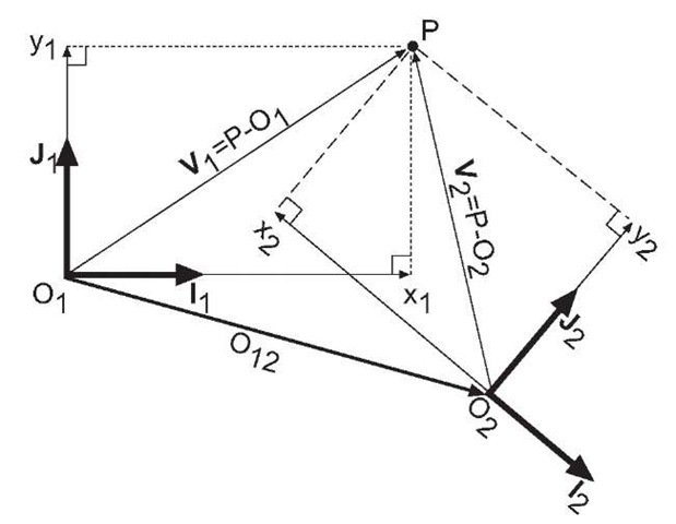
onto the![]() axes. For the two-dimensional x — y plane, the discussion of this paragraph is depicted in Figure 2.9.
axes. For the two-dimensional x — y plane, the discussion of this paragraph is depicted in Figure 2.9.
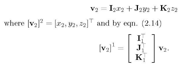
A vector v can be defined without reference to a specific reference frame. When convenient, as discussed above, the representation of![]() with respect to the axes of frame
with respect to the axes of frame![]() is
is
Eqn. (2.14) is used in derivations later in this subsection.
Figure 2.9: Two dimensional representation of the determination of the coordinates of a point P relative to the origin![]() of reference frame.
of reference frame.
With two distinct reference frames![]() the same point can be represented by a different sets of coordinates in each reference frame.The remainder of this section discusses the important question of how to use the coordinates of a point in one frame-of-reference to compute the coordinates of the same point with respect to a different frame-of-reference. The transformation of point coordinates from one frame-of-reference to another will require two operations: translation and rotation.
the same point can be represented by a different sets of coordinates in each reference frame.The remainder of this section discusses the important question of how to use the coordinates of a point in one frame-of-reference to compute the coordinates of the same point with respect to a different frame-of-reference. The transformation of point coordinates from one frame-of-reference to another will require two operations: translation and rotation.
From the above discussion,![]() is the vector from
is the vector from![]() to P and
to P and
![]() is the vector from
is the vector from![]() Define
Define![]() as the vector from
as the vector from![]() Therefore, we have that
Therefore, we have that 
This equation must hold whether the vectors are represented in the coordinates of the![]() frame or the
frame or the![]() frame.
frame.
Denote the components of vector![]() relative to the
relative to the![]() frame as
frame as![]()
![]() the components of
the components of![]() relative to the
relative to the![]() frame as
frame as![]()
![]() and the components of
and the components of![]() relative to the
relative to the![]() frame as
frame as![]()
![]() Assume that
Assume that![]() and the relative orientation of the two reference frames are known. Then, the position of P with respect to the
and the relative orientation of the two reference frames are known. Then, the position of P with respect to the![]() frame can be computed as
frame can be computed as
Because it is the only unknown term in the right hand side, the present question of interest is how to calculate![]() based on the available information.
based on the available information.
Figure 2.10: Definition of the coordinates of a point P with respect to two frames-of-reference![]()
Let![]() represent the unit vectors along the axes. As discussed relative to eqn. (2.14), vectors
represent the unit vectors along the axes. As discussed relative to eqn. (2.14), vectors![]() defined as
defined as
represent the unit vectors in the direction of the![]() coordinate axes that are resolved in the
coordinate axes that are resolved in the![]() reference frame. Since
reference frame. Since![]() are orthonormal, so are
are orthonormal, so are![]() Therefore, the matrix
Therefore, the matrix  is an orthonormal matrix
![]()
Each element of![]() is the cosine of the angle between one of
is the cosine of the angle between one of![]() and one of
and one of![]() To see this, consider the element in the third row second column:
To see this, consider the element in the third row second column:
where![]() is the angle between
is the angle between![]() and we have used the fact that
and we have used the fact that ![]()
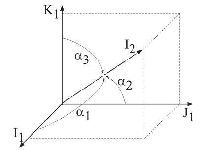
Figure 2.11: Definition of![]() in eqn. (2.16).
in eqn. (2.16).
Because each element of![]() is the cosine of the angle between one of the coordinate axes of
is the cosine of the angle between one of the coordinate axes of![]() and one of the coordinate axes of
and one of the coordinate axes of![]() the matrix
the matrix ![]() is referred to as a direction cosine matrix:
is referred to as a direction cosine matrix:
Figure 2.11 depicts the angles .![]() for
for![]() that define the first column of
that define the first column of![]() The
The![]() angles are defined similarly. When the relative orientation of two reference frames is known, the direction cosine matrix
angles are defined similarly. When the relative orientation of two reference frames is known, the direction cosine matrix ![]() is unique and known.
is unique and known.
Although the direction cosine matrix has nine elements, due to the three orthogonality constraints and the three normality constraints, there are only three degrees of freedom.
Therefore,
Point Transformation
When eqn. (2.17) is substituted into eqn. (2.15) it yields the desired equation for the transformation of the coordinates of P with respect to frame 2, as represented by![]() to the coordinates of P with respect to frame 1, as represented by
to the coordinates of P with respect to frame 1, as represented by![]()
The reverse transformation is easily shown from eqn. (2.18) to be
where we have used the fact that![]() where the last equality is true due to the orthonormality of RJ. Note that the point transformation between reference systems involves two operations: translation to account for separation of the origins, and rotation to account for non-alignment of the axis.
where the last equality is true due to the orthonormality of RJ. Note that the point transformation between reference systems involves two operations: translation to account for separation of the origins, and rotation to account for non-alignment of the axis.
Vector Transformation
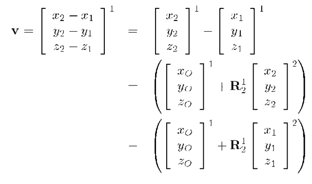
Consider two points![]() Let the vector v denote the directed line segment from
Let the vector v denote the directed line segment from![]() Relative to
Relative to![]() v can be described as
v can be described as
Eqn. (2.20) is the vector transformation between coordinate systems. This relation is valid for any vector quantity. As discussed in detail in [95], it is important to realized that vectors, vector operations, and relations between vectors are invariant relative to any two particular coordinate representations as long as the coordinate systems are related through eqn. (2.20). This is important, as it corresponds to the intuitive notion that the physical properties of a system are invariant no matter how we orient the coordinate system in which our analysis is performed.
In the discussion of this section, the two frames have been considered to have no relative motion. Issues related to relative motion will be critically important in navigation systems and are discussed in subsequent sections.
Throughout the text, the notation![]() will denote the rotation matrix transforming vectors from frame a to frame b. Therefore,
will denote the rotation matrix transforming vectors from frame a to frame b. Therefore,
Matrix Transformation
In some instances, a matrix will be defined with respect to a specific frame of reference. Eqns. (2.21-2.22) can be used to derive the transformation of such matrices between frames-of-reference.
Let![]() be a matrix defined with respect to frame a and
be a matrix defined with respect to frame a and![]()
![]() be two vectors defined in frame a. Let b be a second frame of reference. If
be two vectors defined in frame a. Let b be a second frame of reference. If![]() are related by
are related by  then eqns. (2.21-2.22) show that
or
where
