Two different coordinate systems are common for describing the location of a point in the ECEF frame. These rectangular and geodetic coordinate systems are defined in the following two subsections. Subsection 2.3.3 discusses the transformation between the two types of coordinates.
Figure 2.6: ECEF rectangular coordinate system.
ECEF Rectangular Coordinates
The usual rectangular coordinate system [x, y, z]e, herein referred to as the ECEF coordinate system, has its origin at the Earth’s center of mass with its x-axis extend through the intersection of the prime meridian (0deg longitude) and the equator (0deg latitude). The z-axis extends through the true north pole (i.e., coincident with the Earth spin axis). The y-axis completes the right-handed coordinate system, passing through the equator and 90deg longitude, as shown in Figure 2.6.
The Earth Geoid and Gravity Model
The following sections briefly discuss the need for and definition of the Earth geoid and the gravity model relative to this geoid.
The gravity vector is the vector sum of the gravitational force of the Earth mass and the centrifugal force due to Earth rotation. The relative size and orientation of these two forces is dependent on the point of evaluation. For example, the centrifugal force is maximum at the equator and zero along the Earth axis of rotation. The geodetic surface of the Earth is defined to be everywhere normal to the gravity vector (i.e., an equipotential surface relative to the force of gravity). The geodetic surface is distinct from the actual irregular shape of the surface, but may be imagined as the mean shape that the Earth would take if the solid surface of the Earth were completely covered with sea water.
Earth Geoid
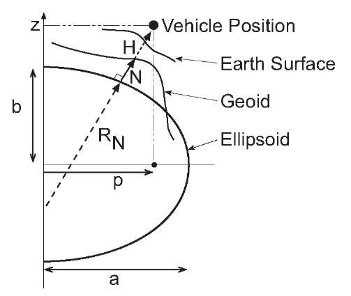
Figure 2.7 illustrates various surfaces useful for understanding the actual shape of the Earth and analytic representations of that shape. The geoid is the mean sea level of the Earth.
Figure 2.7: Definitions of Earth surfaces related to geodetic frame.
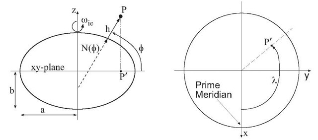
The actual Earth surface fluctuates relative to the geoid. For analytical convenience the geoid is approximated by an ellipsoid created by rotation of an ellipse around its minor axis as shown in Figure 2.8. The center of the ellipsoid is coincident with the center of mass of the Earth. The minor axis of the ellipse is coincident with the mean rotational axis of the Earth.
Most charts and navigation tools are expressed in the![]() geodetic coordinates, as depicted in Figure 2.8, where $ denotes latitude, A denotes longitude, and h denotes altitude above the reference ellipsoid. Latitude is the angle in the meridian plane from the equatorial plane to the ellipsoidal normal N. Note that the extension of the normal towards the interior of the ellipsoid will not intersect the center of the Earth except in special cases such as
geodetic coordinates, as depicted in Figure 2.8, where $ denotes latitude, A denotes longitude, and h denotes altitude above the reference ellipsoid. Latitude is the angle in the meridian plane from the equatorial plane to the ellipsoidal normal N. Note that the extension of the normal towards the interior of the ellipsoid will not intersect the center of the Earth except in special cases such as![]() See Exercise 2.1. Longitude is the angle in the equatorial plane from the prime meridian to the projection of the point of interest onto the equatorial plane. Altitude is the distance along the ellipsoidal normal, away from the interior of the ellipsoid, between the surface of the ellipsoid and the point of interest.
See Exercise 2.1. Longitude is the angle in the equatorial plane from the prime meridian to the projection of the point of interest onto the equatorial plane. Altitude is the distance along the ellipsoidal normal, away from the interior of the ellipsoid, between the surface of the ellipsoid and the point of interest.
A geodetic model is defined by specification of four constants. The eccentricity of the ellipsoid that approximates the geoid is determined by the gravitational attraction and angular rotation rate of the Earth. Therefore, the defining parameters for a geodetic system must be defined consistently to determine the ellipsoid and the gravity model. The parameters of a geodetic model are determined by least squares fitting to experimental data. Various geodetic parameter sets have been defined by different users at different times. The model accuracy has increased along with the associated instrumentation accuracy. In particular,improved accuracy was made possible by the analysis of the trajectories of artificial satellites. This topic will use the WGS84 geodetic system. The WGS84 defining constants are contained in Table 2.1 [12].
Figure 2.8: Geodetic reference coordinate system. Left – Cross section of the ellipsoid containing the rotational axis and the projection of the point P onto the equatorial plane. Right – Cross section of the ellipsoid containing the equatorial plane.
|
Name |
Sysmbol |
Value |
Units |
|
Equatorial radius |
 |
6378137 |
m |
|
Reciprocal flattening |
 |
298.257223563 |
|
|
Angular rate |
 |
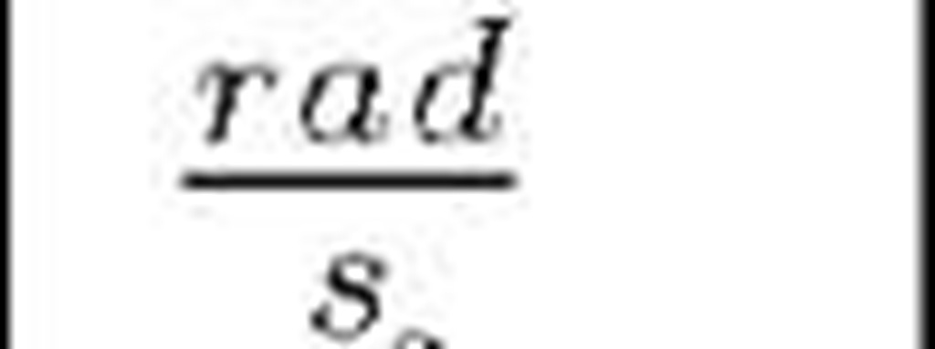
7.292115 x 10~5 |
 |
|
Gravitational constant |
 |
3.986004418 x 10¹⁴ |
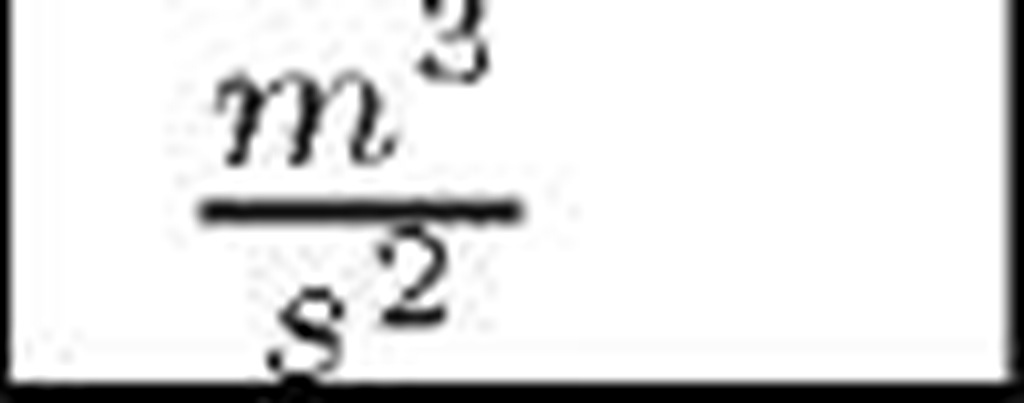 |
Table 2.1: WGS84 defining parameters.
Two constants define the reference ellipse. The ellipse defining parameters are typically the length of the semimajor axis a and one of the following:
Based on the defining constants in Table 2.1, the following ellipse parameter values can be derived:
Replication of the above computations should be completed using machine precision, not the precision displayed in the above results.
For any specific vehicle location, various heights can be defined, as illustrated in Figures 2.7 and 2.8. The geoid height N is the distance along the ellipsoid normal from the ellipsoid to the geoid. The orthometric height H denotes the height of the vehicle above the geoid. It is also referred to as elevation. The altitude or geodetic height can be expressed as h = H + N.
Great circles of a sphere pass through the center of the sphere and divide the sphere into two equal parts. For a point P on Earth’s surface, vertical circles are great circles on the celestial sphere that are perpendicular to the horizon for point P. As such, vertical circles pass through the nadir and zenith for point P. There is a vertical circle for every azimuth angle. Two vertical circles are of particular interest. The vertical circle passing through the north and south horizon points defines the meridian plane of P. The intersection of that plane with the Earth ellipsoid defines the meridian, which is an ellipse of constant longitude (modulo 180 degrees). Let![]() denote the latitude of P. At P the meridian ellipse has radius of curvature .
denote the latitude of P. At P the meridian ellipse has radius of curvature .![]() referred to as the meridian radius or the radius of the ellipse
referred to as the meridian radius or the radius of the ellipse
The vertical circle through the east and west horizon points is the prime vertical. The prime vertical also defines a plane. The radius of curvature at P of the ellipse defined by the intersection of this prime-vertical plane with the Earth ellipsoid is the normal radius
It is also referred to as the prime vertical radius of curvature or the great normal. For![]() the normal radius is the length of the normal to the ellipsoid, from its intersection with the ECEF z-axis to the surface of the ellipsoid. On the reference ellipsoid, parallels are closed curves with constant latitude. Such curves are circles with radius
the normal radius is the length of the normal to the ellipsoid, from its intersection with the ECEF z-axis to the surface of the ellipsoid. On the reference ellipsoid, parallels are closed curves with constant latitude. Such curves are circles with radius![]()
Exercise 2.2 steps through the derivation of eqns. (2.6) and (2.7). Exercise 2.6 asks the user to derive formulas related to eqns. (2.6) and (2.7) that are useful in subsequent derivations.
Earth Gravity Model
The gravity vector varies as a function of position due to the gravitational attraction being a function of geocentric radius, the centripetal acceleration being a function of latitude and radius, and the non-uniform Earth mass distribution.
The WGS84 geodetic and gravity model parameters are defined in Table 2.1. In the geographic reference frame, a local gravity vector model developed by the Defense Mapping Agency that is accurate on the surface of the WGS84 ellipsoid is
where![]() is the latitude,
is the latitude,![]() is the equatorial effective gravity and
is the equatorial effective gravity and
The vector![]() represents local perturbations in the gravity vector relative to the ellipsoidal normal vector. Both
represents local perturbations in the gravity vector relative to the ellipsoidal normal vector. Both![]() are functions of position, but the argument is not shown to simplify the notation.
are functions of position, but the argument is not shown to simplify the notation.
ECEF Transformations
This section presents algorithms to transform between the geodetic (i.e., ![]() and rectangular
and rectangular![]() ECEF coordinates. The WGS- 84 ellipsoid parameters are used throughout the discussion.
ECEF coordinates. The WGS- 84 ellipsoid parameters are used throughout the discussion.
When the geodetic coordinates are known, the coordinates in the ECEF frame is calculated as
Example 2.1 The geodetic position of a point in the vicinity of Los Angeles, CA is![]() degrees, 0 minutes, 0.00174 seconds North,
degrees, 0 minutes, 0.00174 seconds North,![]() degrees, 20 minutes, 0.84965 seconds West, andh = 251.702 m. These coordinates convert to
degrees, 20 minutes, 0.84965 seconds West, andh = 251.702 m. These coordinates convert to![]()
rad. The signs and precision are critical, see Exercise 2.3. Then .![]()
![]() and
and
Readers unfamiliar with the degrees, minutes, seconds notation should see Exercises 2.3 and 2.4. A
The transformation from![]() to geodetic coordinates is more involved, but is important in GPS applications where the ECEF rectangular coordinates are directly determined from range measurements and the geodetic coordinates are often desired. Longitude can be found explicitly from eqns. (2.9-2.10) as
to geodetic coordinates is more involved, but is important in GPS applications where the ECEF rectangular coordinates are directly determined from range measurements and the geodetic coordinates are often desired. Longitude can be found explicitly from eqns. (2.9-2.10) as![]() Solution for h and
Solution for h and![]() can be computed by iteration as follows [92]:
can be computed by iteration as follows [92]:
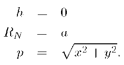
1. Initialization: Let
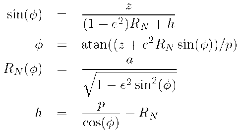
2. Perform the following iteration until convergence:
where the eccentricity e is a defining constant of the geodetic system as discussed in Section 2.3.2.1. Although it is conceptually simpler to take the inverse sine in the second step, the presented algorithm has much faster convergence, as shown in the following example.
Example 2.2 Consider the inversion of the previous example in which
Starting with an initial estimate of h =0.0 m, the algorithm as written converges to centimeter accuracy![]() in four iterations:
in four iterations:
|
iteration |
1 |
2 |
3 |
4 |
5 |
|
lat: deg |
34 |
34 |
34 |
34 |
34 |
|
lat: min |
0 |
0 |
0 |
0 |
0 |
|
lat: sec |
0.027145 |
0.003159 |
0.001738 |
0.001740 |
0.001740 |
|
h |
237.6519 |
251.7325 |
251.7020 |
251.7020 |
251.7020 |
The same algorithm with the same initial estimate for h, but using an inverse sine instead of an arctan function in the second calculation of the iteration has still not converged to meter level accuracy after eight iterations:
|
iteration |
1 |
2 |
3 |
4 |
5 |
6 |
7 |
8 |
|
lat:deg |
34 |
33 |
34 |
33 |
34 |
33 |
34 |
33 |
|
lat: min |
2 |
58 |
0 |
59 |
0 |
59 |
0 |
59 |
|
lat: sec |
31.41 |
50.62 |
31.77 |
45.45 |
6.67 |
56.95 |
1.40 |
59.36 |
|
h |
3401 |
-1189 |
912 |
-50 |
390 |
188 |
280 |
238 |
Convergence to centimeter accuracy requires 25 iterations. Generally, the arctan-based iterative technique converges quickly, especially when a good initial guess at the solution (e.g., from a previous measurement) is available.
Various alternative approximate and closed form solutions exist in the literature [24, 66, 68, 76, 117].

