The previous sections have motivated the necessity of maintaining accurate direction cosine matrices. The following two subsections will consider two methods for maintaining the direction cosine matrix as the two reference frames experience arbitrary relative angular motion. Each technique relies on measuring the relative angular rate and integrating it (via different methods). Initial conditions for the resulting differential equations are discussed in Sections 10.3 and 11.7. Prior to integration, the angular rates should be properly compensated for biases and navigation frame rotation as discussed in Section 11.3.
The measurement of angular rates followed by integration to determine angle has the disadvantage that measurement errors will accumulate during the integration process. However, the approach has several distinct advantages. The angular rates are measurable via inertial measurements. Inertial measurements do not rely on the reception of any signal exterior to the sensor itself. Therefore, the accuracy of the measurement and integration processes will only be limited by the accuracy inherent to the instrument and of the integration process. Both of these quantities can be accurately calibrated so that the system accuracy can be reliably predicted. Also, the error accumulation through the integration of inertial quantities is a slow process that can be corrected via aiding sensors. Alternatively, level sensors and compass type instruments could be used to directly measure the Euler angles. However, level (gravity vector) sensors are sensitive to acceleration as well as attitude changes; and, yaw/heading sensors are sensitive to local magnetic fields. The resulting measurement errors are difficult to quantify accurately and reliably at the design stage.
Direction Cosine Derivatives
Eqn. (2.53) provides a differential equation which can be integrated to maintain the direction cosine matrix. Such an approach could numerically integrate each of the direction cosine elements separately; however, since the equation is linear, a closed form solution should be obtainable. Direct numeric integration of eqn. (2.53) does not enforce the orthogonality nor normality constraints on the direction cosine matrix; hence, additional normalization calculations would be required.
Let![]() and select T sufficiently small that
and select T sufficiently small that![]() can be considered constant
can be considered constant![]() To derive a closed form solution to eqn. (2.53) with initial condition
To derive a closed form solution to eqn. (2.53) with initial condition![]() define the integrating factor
define the integrating factor
where![]() has been used as a shorthand notation for
has been used as a shorthand notation for![]() to decrease the complexity of the notation. The
to decrease the complexity of the notation. The![]() notation is defined in eqn. (B.15).
notation is defined in eqn. (B.15).
Multiplying the integrating factor into eqn. (2.53) and simplifying, yields 
where the last step is valid given the assumption that T is sufficiently small so that![]() is constant over the period of integration. Integrating both sides, over the period of integration yields
is constant over the period of integration. Integrating both sides, over the period of integration yields
To simplify this expression, let
where![]() Powers of the matrix
Powers of the matrix![]() reduce as follows:
reduce as follows:
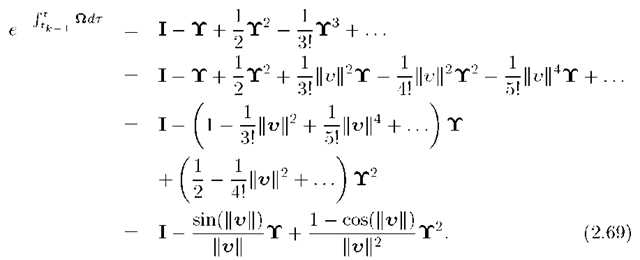
which are verified in Exercise 2.10. Therefore, using eqn. (B.42),
Substituting eqn. (2.69) into eqn. (2.63) yields
where![]() Eqn. (2.70) is properly defined theoretically, even as
Eqn. (2.70) is properly defined theoretically, even as![]() but must be implemented numerically with care.
but must be implemented numerically with care.
The designer must ensure that the interval![]() is sufficiently small (i.e., the sample frequency is sufficiently fast) to satisfy the assumption above eqn. (2.62) that each
is sufficiently small (i.e., the sample frequency is sufficiently fast) to satisfy the assumption above eqn. (2.62) that each![]() can be considered constant over each period of integration.
can be considered constant over each period of integration.
Euler Angle Derivatives
Section 2.5 defined the Euler angles![]() and described their use to determine the direction cosine matrix
and described their use to determine the direction cosine matrix![]() This method of determining the direction cosine matrix requires the navigation system to measure or compute the Euler angles. This section presents the method for computing the Euler angle derivatives
This method of determining the direction cosine matrix requires the navigation system to measure or compute the Euler angles. This section presents the method for computing the Euler angle derivatives![]() from the angular rate vector
from the angular rate vector![]() The navigation system could then integrate the Euler angle derivatives, to determine the Euler angles from which the direction cosine matrix can be computed.
The navigation system could then integrate the Euler angle derivatives, to determine the Euler angles from which the direction cosine matrix can be computed.
Note that the three-tuple![]() is not related to
is not related to![]() by a rotational transform because each of the components of
by a rotational transform because each of the components of![]() is defined in a different reference frame. Instead, we have that
is defined in a different reference frame. Instead, we have that
Figures 2.14-2.16 define the yaw, pitch, and roll rotations. In addition, the figures show that![]() is the rate of rotation about the K or
is the rate of rotation about the K or![]() axes, which
axes, which ![]() are coincident; that _ is the rate of rotation about the
are coincident; that _ is the rate of rotation about the![]() axes, which
axes, which
are coincident; and, that![]() is the rate of rotation about the
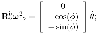
is the rate of rotation about the![]() axes, which are coincident. From the facts in the previous sentence we have that
axes, which are coincident. From the facts in the previous sentence we have that
From eqn. (2.71) we have
From eqn. (2.42),
and from eqns. (2.41-2.42),
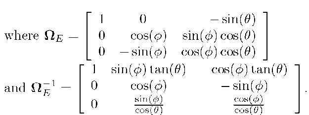
Therefore, eqn. (2.72) yields
The inverse transformation is
Neither![]() nor its inverse is a rotation matrix. Eqns. (2.73) and (2.74) do not represent vector transformations between frames-of-reference. The matrix
nor its inverse is a rotation matrix. Eqns. (2.73) and (2.74) do not represent vector transformations between frames-of-reference. The matrix![]() is singular when
is singular when![]()
Eqn. (2.74) is a nonlinear ordinary differential equation for the Euler angles. Numeric integration of eqn. (2.74) provides estimates of the Euler angles from which the direction cosine matrix can by computed using eqn. (2.43). This approach requires numerous trigonometric operations at the high rate of the attitude portion of the INS system.


