In 1998, the European Space Agency (ESA) and the European Commission jointly decided to study the feasibility of a truly independent European GNSS. Named Galileo, the program was first approved in 1999. Besides being independent, Galileo is expected to offer greater accuracy, integrity, availability, and continuity of services compared to present systems. In spite of the dual-use nature of any GNSS system, Galileo is intended for civilian application only. It has been deemed a "civil programme under civil control."
Being civilian-friendly means that, so far, none of Galileo’s funding has come directly from defence budgets. With deployment costs estimated between €3.2-3.6 billion, funding is expected to come from public-private partnerships (PPP) and fee-for service charges to be collected by the Galileo Operating Company (GOC). Total costs, including 12 years of operational costs, are likely to reach €6 billion. With respect to partnerships, the European Investment Bank and a number of private enterprises are collectively planning to pledge a minimum of €5 million to the project. They may team up with Joint Undertaking (JU), which is presently responsible for the development and validation phase. To avoid conflicts of interest, private enterprises may not become members until the tendering process has finished.
Architecture Like any GNSS, Galileo consists of the space segment, the ground segment, and the user receiver. The space segment will be comprised of 30 satellites (27 active and 3 spare) in the Medium Earth Orbit (MEO) at an altitude of 23600km. The satellites will travel along three circular orbits at an inclination of 56°, ensuring global coverage. With a satellite orbit time of 14 hours, the configuration of the constellation will guarantee at least six in-sight satellites at any given time for any location, including the poles.
The Galileo satellites will have an expected lifespan of 10 years. Individual satellites will be replaced on a regular basis to account for eventual malfunctioning, residual life, and accommodation of future payload technology.
The space segment will be managed by two control centres located in Europe, supported by 20 Galileo Sensor Stations (GSS). Data exchanges between the control centres and the satellites will be carried out through specific uplink stations. A total of 15 uplink stations will be installed around the world to facilitate this type of data transfer. As the principal component of the ground segment, the control centres will be responsible for the management of the satellites, the integrity of the signals, and the synchronisation of the atomic clocks onboard the satellites.
Galileo Signals and Services Galileo satellites will transmit ten different signals located on the following bands: E5a and E5b (11641215MHz), E6 (1260-1300MHz), and E1-L1-E2 (1559-1592MHz). Six signals will be devoted to civilian (Open Service) and Safety of Life (SoL) services, two for commercial users, and the remaining two (Public Regulated Services, or PRS) for official/regulated personnel. Apart from these timing and navigation transmissions, Galileo will provide information concerning the accuracy and status of its signals. Known as "integrity messages," these signals are specifically geared for SoL applications, although they are likely to be offered to service industries requiring legal guarantees (during the transportation of valuable goods, for example). The services offered by Galileo are as follows:
■ The Open Service (OS) will be available to civilian users free of charge and will accurately provide positioning, speed, and UTC time. According to the plans of the European Commission, the quality of the OS will be better than that of the present and future GPS civil services. It will be offered by the E5a, E5b, and E1-L1-E2 bands.
■ The Commercial Service (CS) will operate under a fee-for-service plan. As such, access to the CS will require a payment to the GOC through the service provider in return for the encryption keys required to receive the signals. Compared to the OS, CS signals will be of a higher quality and will guarantee a certain level of reliability and accuracy. Service will be provided by signals located on E5b, E6, and E1-L1-E2 bands.
■ The SoL service will offer the same accuracy as the OS but with a high level of integrity. A greater level of integrity is required for an effective and accurate service for companies working in the field of air and maritime navigation. At some stage, SoL may be encrypted and therefore require a fee for access. The Search and Rescue (SAR) service will be a certified service developed in accordance with international regulations. It will provide real-time transmissions of emergency requests to facilitate the location of distress messages. SoL will be provided by the signals on the E5a, E5b, and E1-L1-E2 bands and will be a restricted service.
■ The Public Regulated Services (PRS) signal will be for governmental use only and is designed to guarantee continuous signal access in the event of threats or crisis. It will require noncommercial receivers that can store the needed decryption keys and will be provided by signals on the E6 and L1 bands. An access-regulated service such as the SoL will also be required.
The goal of this topic is to explain the design process of a receiver that will offer basic services to the user. Thus, signals on the E5a, E5b, and E1-L1-E2 bands that make up the Open Service will be described in detail.
Signals on the E5 Band Four different signals are sent on the E5 band with a central frequency of 1191.795MHz; E5a and E5b have two components in quadrature each one. The signal modulation is the alternative BOC, AltBOC(15,10). The signal processing techniques required to process AltBOC modulation are much more challenging than those used for traditional BPSK or even for usual BOC modulation. This stems from the extremely large bandwidth and from the complex interaction of four components of the spreading code. It can be assumed that the four signal components on the E5 band are modulated as a single wideband signal generated following AltBOC(15,10) 8-PSK modulation. This wideband signal is centred on the E5 frequency of 1191.795MHz and has a bandwidth of at least 70MHz. AltBOC modulation offers the advantage that the E5a (I&Q) and E5b (I&Q) bands can be processed independently, like traditional BPSK(10) signals, or together, leading to tremendous performance in terms of tracking noise and multipath functions. Characteristics of all four signals are summarized in Table 2-2.
Signals on the E1-L1-E2 Band The E1-L1-E2 band is composed of three channels sent by the same carrier (fL1 = 1575.42MHz) and modulated through the "modified hexaphase modulation." In baseband, channels B and C will show a BOC(1,1) modulation, while coded information will be sent through flexible modulation BOC(15,2.5) on channel A.
TABLE 2-2 Characteristics of the components of the E5 signal band
|
Signal component |
Modulation |
Data |
Centre frequency |
|
E5aI |
BPSK(10) |
Yes |
1176.45MHz |
|
E5aQ |
BPSK(10) |
No |
1176.45MHz |
|
E5bI |
BPSK(10) |
Yes |
1207.14MHz |
|
E5bQ |
BPSK(10) |
No |
1207.14MHz |
TABLE 2-3 Signals sent by Galileo satellites
|
Frequency band |
E1-L1-E2 |
E5 |
|
Channels |
A B C |
I Q |
|
Frequency |
1575.42MHz |
1164-1214MHz |
|
Modulation type |
 |
|
|
Bit rates |
||
|
Minimum received power @ elevation 10° |
||
Description of Galileo Signals Table 2-3 summarises the signals of the Galileo satellites that provide the OS. The service will be operative starting in 2012.
GPS and Galileo Interoperability
After analysing the signals of the GPS and Galileo navigation systems, it can be seen that there are two frequency bands where both systems simultaneously send the navigation message: GPS L1 with Galileo E1-L1-E2 and GPS L5 with Galileo E5 (see Figure 2-7). A GPS/Galileo multistandard terminal should receive signals from one or both frequency bands and be able to provide the position with one or both systems at the same time.
This topic aims to show the design process of a RF front-end that receives the signals of the first frequency band, namely GPS L1 and Galileo E1-L1-E2, so the receiver can relay position data with one or both systems at the same time. As the E1-L1-E2 signal bandwidth (24MHz) is higher than the L1 signal (2.046MHz), the former will establish the bandwidth of the input signal that has to be processed.
Figure 2-7 Signals bands sent by Galileo [Chatre05] and GPS [Stansell06]
Once the signals to be received by the front-end are identified, requirements for the receiver have to be defined. Specifications regarding noise, linearity, and bandwidth must be studied to obtain a reliable and accurate positioning through GPS and/or Galileo.
System Analysis
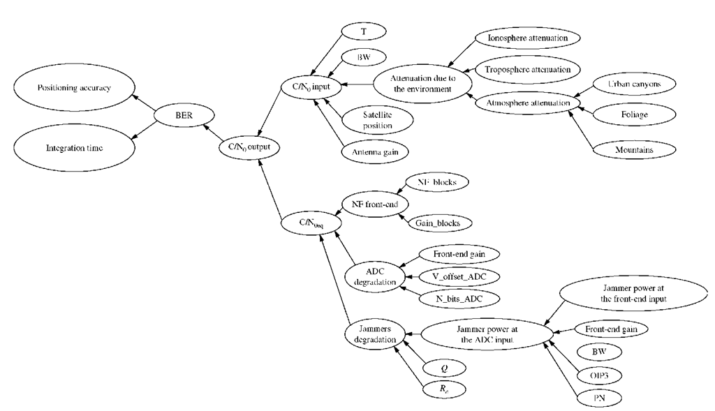
This section deals with the establishment of the specifications for a dual RF GPS/Galileo RF front-end, which is required for proper design and fabrication. The receiver’s noise figure, third-order intermodula-tion product (IP3), and bandwidth requirements are taken from the GPS and Galileo standards analysed in the previous section. These parameters typically determine sensitivity, the lowest signal power that can be received; linearity, which is related to highest signal power that can be received and the frequency bandwidth of the receiver. All these parameters are related to the positioning accuracy and integration time through the BER as it is shown in the Figure 2-8.
The manner in which these are obtained is explained in detail in this section, along with the receiver architecture and the receiver blocks: receiver chain and phase-locked loop (PLL) specifications.
System Specifications
As with any other RF front-end, the parameters that characterise the receiver are the noise figure, linearity, and frequency bandwidth, which will be explained in the following subsections.
Noise Figure GNSS signals are transmitted by medium power satellites, with approximately 40dBm. When they reach the Earth, they are normally received by low-gain, low-power quasi-omnidirectional antennas with a minimum power of approximately -131dBm. Thus, multiple-access noise can be considered second-order noise rather than thermal or white noise. Moreover, [Parkinson96] explains that the transmission channel adds only Gaussian-distributed white noise.
First of all, the BPSK-modulated GPS L1 signal is considered. The error probability for the demodulation of a BPSK signal sent through a channel that considers Gaussian distributed noise can be calculated by Eq. 2-5.
where![]() is the energy per bit,
is the energy per bit,![]() is the power of the received signal, C is the power of the received signal in 1Hz, and
is the power of the received signal, C is the power of the received signal in 1Hz, and![]() is 50bps of the navigation message. This provides a valuable parameter to measure the performance quality of the front-end when it comes to the lowest signal power it can detect: the carrier-power-density-to-noise ratio (C/N0), which is typically given in decibels.
is 50bps of the navigation message. This provides a valuable parameter to measure the performance quality of the front-end when it comes to the lowest signal power it can detect: the carrier-power-density-to-noise ratio (C/N0), which is typically given in decibels.
Figure 2-8 Relationship between various parameters of a GNSS receiver
The carrier-to-noise ratio (C/N0) is related to the maximum bit error rate (BER) required for a GPS receiver at the output, which is 10-5 [Parkinson96]. Eq. 2-5 demonstrates that C/N0fd should be above 10 to achieve the necessary BER. If the navigation message has a frequency of 50bps, then the minimum required C/N0 at the output of the RF front-end will be 27dB/Hz. On the other hand, thermal noise density at the input of the antenna is typically -174dBm/Hz and the minimum received input power in the case of GPS is -131dBm[ARINC00]. Therefore, C/N0 at the input of the RF front-end results in 43dB/Hz. Thus, the maximum allowed noise figure can be obtained from the difference between the minimum expected C/N0 at the input and the minimum required C/N0 at the output, which comes out to 16dB.
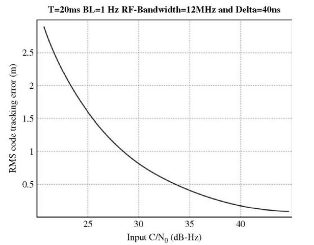
Let’s now move to the BOC (1,1)-modulated E1-L1-E2 Galileo signal. To ensure correct positioning for different receiver designs, the digital part of the receiver must have at least a C/N0 of 30dB/Hz at the output of the RF front-end[Hein02]. Such a C/N0 does not imply an error in the demodulation, it only means a higher or lower accuracy positioning. Figure 2-9 shows how RMS error in metres, due to code tracking error, increases exponentially for values of C/N0 below 30dB/Hz. The thermal noise density at the input of the antenna is typically -174dBm/Hz and the minimum received signal power can be estimated as -128dBm.
Figure 2-9 RMS code tracking error in metres
Therefore, the C/N0 at the input of the RF front-end is 46dB/Hz. Thus, the maximum allowed noise figure (NF) for correct positioning can be set at 16dB. As was calculated for the GPS case, this is the difference between the minimum C/N0 at the input and the minimum required C/N0 at the output.
As the C/N0 values employed for the calculations have been set to meet minimum requirements for a receiver the obtained NF values are the maximum ones allowed. However, not only the NF but also the integration time (T) of the receiver and the signal detection probability determine the quality of the receiver. For a better understanding of the relation among these parameters, an explanation of how a receiver acquires the signal is first required.
The signal acquisition process is a search process where it is necessary to repeat the C/A of the satellite from which the signal is received and the carrier frequency of the modulated code. The received carrier signal presents a frequency variation due to the Doppler Effect as a result of the speed of the satellite in its orbit and the speed of the receiver.
Figure 2-10 shows the bidimensional searching process. The generated C/A-code phase and the generated carrier frequency are swung, obtaining cells that are compared with the received signal by a correlation process. Every cell correlation process lasts T seconds. The decision to maintain or discard the signal is taken by comparing the value obtained in the correlation process with a given threshold value.
Figure 2-10 Bidimensional searching process
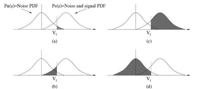
Figure 2-11 (a) False alarm probability. (b) False discard probability. Although there is a signal, it is not detected. (c) Signal detection probability. (d) Correct discard probability.
Every comparison has its probability density function (PDF); as there is noise with or without the signal in every cell, the detection process is a statistical one.
Figure 2-11 shows the probability density functions for the reception of the GPS L1 signal, when the decision is taken in the first try. If the obtained value is higher than a threshold value, the signal may be maintained; otherwise, it will be discarded. The signal detection probability![]() and the false alarm probability
and the false alarm probability![]() when maintaining the signal is considered in its absence, can be analytically expressed by Eq. 2-6 and Eq. 2-7.
when maintaining the signal is considered in its absence, can be analytically expressed by Eq. 2-6 and Eq. 2-7.
where![]() is the probability density function in the presence of the signal,
is the probability density function in the presence of the signal,![]() is the probability density function in the absence of the signal, and
is the probability density function in the absence of the signal, and![]() is a given threshold value.
is a given threshold value.
As phase I and quadrature Q L1 signals are Gaussian distributed, probability density functions![]() can be calculated by Eq. 2-8 and Eq. 2-9[Kaplan96].
can be calculated by Eq. 2-8 and Eq. 2-9[Kaplan96].
where:
■ s/n is the signal-to-noise ratio estimated before signal detection ![]()
■ S/N is the signal-to-noise ratio estimated before signal detection in decibels and can be calculated by![]()
■ T is the integration time for every cell before signal detection.
■ an is the root means square (RMS) noise power.
For threshold value![]() defined by Eq. 2-10 and a
defined by Eq. 2-10 and a![]() of 16 percent, the signal detection probability
of 16 percent, the signal detection probability![]() can be calculated from Eq. 2-6 and Eq. 2-8. This results in Table 2-4, which shows
can be calculated from Eq. 2-6 and Eq. 2-8. This results in Table 2-4, which shows![]() depending on
depending on![]() and T for a normalised unity
and T for a normalised unity![]()
The values in Table 2-4 can only be considered a guide as it takes commercial receivers more than one attempt to decide whether to maintain or leave a signal out . The values of the table have been shown here for a better understanding of the relation among the noise figure, signal detection probability, and integration time. Consequently, a proper noise figure can be obtained according to the features of the receiver.
As shown in Table 2-4, the higher C/N0 is, the higher the signal detection probability will be, if it exists. This would, in turn, result in shorter integration time, which results in better receiver performance. This is why this process will require a lower noise figure than the previously defined maximum of 16dB, although it could sufficiently provide for accurate GPS or Galileo positioning.
TABLE 2-4 Detection probability versus![]() and integration time T
and integration time T
Another reason for requiring a lower noise figure lies in the increasing use of GNSS receivers in urban environments. The received signal power is reduced in places with high buildings and narrow streets, reaching values of C/N0 around 15dB/Hz in some cases. In this case, the receiver is unable to detect the satellite signal or provides an imprecise position. Moreover, another factor to consider in urban environments is the presence of interference signals that the receiver can capture, increasing SNR degradation.
A maximum noise figure of 3.5~4dB has been defined taking all these reasons into account. These values have been taken from an exhaustive study of commercial GPS receivers, making the receiver compatible with any detection method used today.
Linearity Receiver linearity requirements for GPS and Galileo receivers are not critical when it comes to the received signal because the power received is very low and practically constant. Linearity requirements are therefore imposed by receiver behaviour to external interferences. Section 2.2.2.3 shows a wider study of this behaviour.
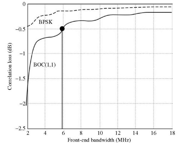
Bandwidth As mentioned in section 2.1.3, the bandwidth of the Galileo signal is higher than that of the GPS signal. To be able to receive all the information sent, designers should choose the highest bandwidth. Nevertheless, lower bandwidth filters lower than those set by the standard can be applied without major damage to the C/N0. Figure 2-12 shows the correlation loss due to the bandwidth of the filter used for signal reception.
Figure 2-12 C/N0 degradation versus receiver bandwidth
Figure 2-13 Power spectral density of a BOC (1,1) and BPSK-modulated signals
It can be seen that for a filter with a bandwidth higher than 14MHz, the degradation of C/N0 is less than 0.25dB and losses increase exponentially for a filter with a bandwidth lower than 6MHz. Therefore, a 6MHz bandwidth is specified for the RF front-end to avoid degradation higher than 0.5dB and to be able to filter interferences in neighbour bands. It improves the C/N0 ratio and sensitivity due to lower noise bandwidth.
Figure 2-13 shows that the specified bandwidth comprises the two main lobes of the Galileo BOC (1,1) signal as well as the main lobe of the GPS C/A-code with its two side lobes.
![Signals bands sent by Galileo [Chatre05] and GPS [Stansell06] Signals bands sent by Galileo [Chatre05] and GPS [Stansell06]](http://what-when-how.com/wp-content/uploads/2012/02/tmpE147_thumb2_thumb.jpg)
![tmpE-148_thumb[2] tmpE-148_thumb[2]](http://what-when-how.com/wp-content/uploads/2012/02/tmpE148_thumb2_thumb.png)


![tmpE-163_thumb[2] tmpE-163_thumb[2]](http://what-when-how.com/wp-content/uploads/2012/02/tmpE163_thumb2_thumb.jpg)
![tmpE-172_thumb[2] tmpE-172_thumb[2]](http://what-when-how.com/wp-content/uploads/2012/02/tmpE172_thumb2_thumb.jpg)
![tmpE-189_thumb[2] tmpE-189_thumb[2]](http://what-when-how.com/wp-content/uploads/2012/02/tmpE189_thumb2_thumb.png)


