Introduction
Car traffic has increased dramatically. Although additional traffic regulations, such as speed limits, and other restrictions were imposed to reduce accidents, crashes can be seen every day. Many result in vehicle damage or injuries to occupants or others. Claims resulting from these accidents often have to be settled in court.
In most countries special ‘accident experts’ assist judges in reconstructing accident situations, based, for example, on information from eyewitnesses, car deformations or tire marks. In many countries these experts are either specially trained police officers or members of the road authorities. In others, reconstructions are performed by independent specialists. These accident analyses, which form the basis for court decisions, were the start of specific accident research.
Accidents are also reconstructed for many other reasons. Car manufacturers perform in-depth studies of real accidents to learn more about accident mechanisms and to study the potential and the effectiveness of new safety devices in cars. Accidents are also often reconstructed and analyzed to help improve road planning.
There are several questions that must be answered when reconstructing a car accident. Today’s accident reconstruction tries to provide full information about the movement of all involved vehicles, persons or objects from the point of first visual contact to their rest positions. Time history of velocities, positions and crash-related data, such as velocity changes, deformation energies and passenger loads, must be analyzed. In addition, prevention analyses are often included. These analyses allow determination of the conditions necessary to prevent repetition of the accident.
There is one general rule in any accident reconstruction: a detailed collection of scene data forms the basis for a good reconstruction. Some of the most important scene data are:
• vehicle or human rest positions;
• road marks;
• vehicle damages and marks;
• personal injuries.
Owing to the increased number of cars with ABS, fewer tire marks, which formed the most objective basis, can be seen and thus one major contribution to the reconstruction is lost. On the other hand, the increased performance of personal computers has made it possible to use highly sophisticated reconstruction or simulation algorithms to study accidents.
In recent years several software products have been developed for the reconstruction of vehicle accidents. Some of them are designed just to calculate vehicle velocities from the kinematics of specific accident types. Others, with full vehicle simulators, allow the simulation of car motion during the accident, starting from the point of reaction to the end position for any kind of accident. It is now even possible to visualize the car motion on the screen during the calculation in real time. Three-dimensional geometric information regarding road marks can be imported from CAD systems or from photographs as scanned bitmaps, and all important road, car and tire characteristics can be taken into account, as well as the reactions of the driver.
Targets
It is important, when formulating the physical and mathematical model of a car, to take into account the fact that many parameters are not well known when reconstructing the accident. In particular, the condition of the tires, such as their age or air pressure, the dampers or the steering system are often not well documented. The resistance of the chassis is only known for well-defined crash conditions and not for the specific accident situation. Therefore it is important to find a compromise between accuracy and the amount of input data necessary to perform the calculation. On the other hand, the user should be able to take into account all parameters which are documented and known to influence driving and crash behavior. Based on this knowledge, simplified models have to be used, which guarantee that the basic driving behavior is predicted correctly. All necessary input parameters must be defined on the basis of physical parameters and a simple means of varying the parameters guarantees that the expert can crosscheck their influence on the simulation result.
The automotive industry uses several simulation models to learn about the driving behavior of vehicles. These industrial vehicle dynamics simulation programs are optimized to predict driving behavior under well-defined initial and boundary conditions. As a result these models require many input parameters. For the reconstruction of a vehicle accident, such detailed knowledge, especially regarding the suspension, the tires and the road conditions, is normally not available. In addition, the steering and degree of braking are often not known. It is thus difficult to use these simulation models for the reconstruction of vehicle accidents.
A similar problem exists regarding collision models. Several programs (mainly finite element (FE)-based) exist that allow the calculation of the deformations for well-defined collision conditions. To achieve good agreement with real impacts, they require a very detailed knowledge of the vehicle structure and a very powerful computer. Some 100 000 degrees of freedom are required to model one vehicle properly. In addition, every simulation has to be calibrated with similar crash tests. This is the major reason why FE programs are only used for accident reconstruction in a few specific cases.
Several computer programs have been developed especially for the reconstruction of vehicle accidents. They allow the calculation of vehicle motion and collisions based on various physical models. PC-CRASH is one of these programs with a worldwide distribution. It uses a kinetic time forward simulation of vehicle dynamics and combines it with a momentum-based collision model; accidents can be reconstructed, starting from the point of reaction to the end position, for all involved cars simultaneously. The reconstruction is performed in an interactive graphical environment, which allows a sketch or photograph of the accident scene to underlay the reconstruction. For an effective presentation of the results, 3D animations can be created directly from the calculated results.
Accident Analysis
Postcrash movement
In a conventional accident analysis the reconstruction is normally started from the rest positions of the involved vehicles and calculated backwards to the collision position. To determine the postcrash velocity of the vehicles, an average deceleration has to be estimated. In many cases, where no tire marks are available, straight-line movement of the vehicle is assumed for determining the distance of postcrash travel. Depending on the road situation and involved vehicle, an average deceleration level is assumed, typically in the range of 0.1-10 ms-2. The postcrash velocity can than be calculated according to the formula:

where v represents the postcrash velocity (ms-1), a the average deceleration (ms-2)and s the postcrash travel of the vehicle’s center of gravity (m).
The major problem with this method is estimating the vehicle’s average deceleration during a complicated postcrash movement. In this phase the vehicle may have been rolling or sliding and this has a huge influence on the amount of energy dissipated. To overcome this problem, vehicle simulators are often used to compare the vehicle’s movement with marks found on the road or on the vehicle. Thus the post-crash velocity can be determined more accurately.
Collision model
During the collision the contact forces between the two involved vehicles vary over time. These forces depend on the vehicle structure, the deformation velocity, the contact situation and several other parameters. As these dependencies are highly nonlinear and very difficult to formulate, the treatment of the parameters through their integral values has proven to be more efficient. Modern FE programs allow investigation of the time variation of the contact forces. But these programs require enormous calculation times and a huge amount of modeling. Simplified models like the CRASH algorithm have produced large errors under several conditions. In many cases, insufficient knowledge regarding the structural deformation behavior is available to estimate the proper parameters.
Crash hypotheses that only compare the velocity conditions of both vehicles before and after the impact have therefore been used with great success for the reconstruction of accidents.
Material properties in the contact area During the contact phase large forces may occur, which cause deformations to one or both collision partners. These deformations may remain fully or partially after the impact (plastic deformations) or they may fully recover (elastic deformations). Through the definition of the parameter k the amount of elasticity for a crash can be defined. This parameter k is only valid for a whole crash situation and not for one of the partners. Therefore one crash partner may exhibit a high degree of elasticity when impacting with partner A and a high degree of plasticity when impacting with partner B.
Using an example of a straight central impact (Fig. 1), the parameter k can be easily explained. To insure that the two partners collide, the velocity of partner 1 must be higher than the velocity of partner 2. In phase 1 contact forces act, which reduce the velocity of mass 1 and increase that of mass 2. They are equivalent in size, but with opposite direction. The relation between acceleration and contact force is calculated from:
![]()
where m defines the mass, a the acceleration and F the contact force. The end of phase 1 is defined when both partners have equal velocities. It is called the ‘compression’ phase. In phase 2 the forces reduce again until the two masses separate. This phase 2 is called ‘restitution’.
In this case the coefficient of restitution is defined
as

0 < k < 1 where k=0 represents a fully plastic and k=1 a fully elastic impact.
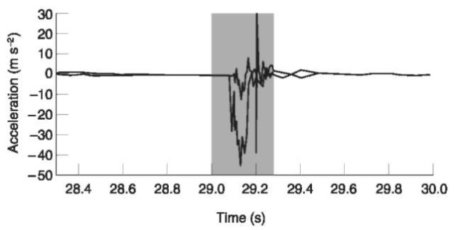
Eccentric impacts Figure 2 shows an example of a measurement of the two acceleration components for an eccentric impact. The compression moment Sc and restitution momentum SR are now defined as
![tmp2B38_thumb[2] tmp2B38_thumb[2]](http://lh4.ggpht.com/_1wtadqGaaPs/TFBwspQhdeI/AAAAAAAALCM/rNI_ndahakQ/tmp2B38_thumb2_thumb.png?imgmax=800)
where t0 is the time of first contact, tm defines the time of identical velocity for both vehicles at the point of impact and t1 describes the time of separation.
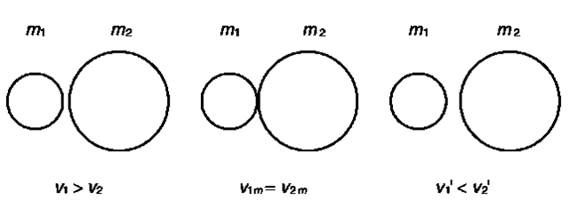
Figure 1 Central impact. See text for explanation.
Figure 2 Measured accelerations.
In the case of a generic eccentric impact, the ‘coefficient of restitution’ is now defined as a ratio between restitution momentum and compression momentum

The total exchanged momentum is calculated from

In a full impact the velocities of both vehicles at the impulse point must be identical at the end of the compression phase (Fig. 3). For simplicity, the impact model is only derived here in 2D. In some programs like PC-CRASH the models are also extended to 3D. They are identical except that all velocities, the momentum and angular momentum are defined in 3D coordinates and all three components of the velocity and rotational velocity are taken into account.
As can be seen in Fig. 3 a local coordinate system is defined, which originates at the ‘impulse point’. The components of the relative velocity for both vehicles at the impulse point can be calculated from:

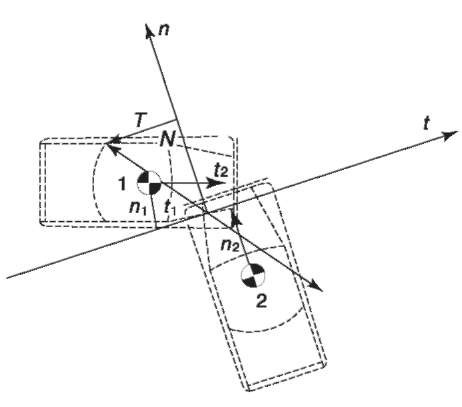
where V/t defines the velocity component of the impulse point for vehicle 1 in direction t and V/„ in direction n. So the components of the relative velocity for both vehicles at the impulse point can be calculated from
![tmp2B45_thumb[1] tmp2B45_thumb[1]](http://lh5.ggpht.com/_1wtadqGaaPs/TFBw4_tVuYI/AAAAAAAALDE/cJkFXsC6v0c/tmp2B45_thumb1_thumb.png?imgmax=800)
In addition, the balance of momentum can be formulated for both vehicles
![tmp2B46_thumb[2] tmp2B46_thumb[2]](http://lh6.ggpht.com/_1wtadqGaaPs/TFBxB5A-MkI/AAAAAAAALDM/ujKMRbUyQS4/tmp2B46_thumb2_thumb.png?imgmax=800)
The balance of angular momentum can be formulated
![tmp2B47_thumb[4] tmp2B47_thumb[4]](http://lh6.ggpht.com/_1wtadqGaaPs/TFBxDtMPpLI/AAAAAAAALDU/p73beOXyoZc/tmp2B47_thumb4_thumb.png?imgmax=800)
When combining these equations, the change of the relative velocity for both vehicles at the impulse point can be calculated from
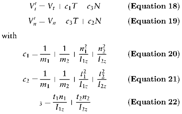
To be able to solve these equations and to calculate the postimpact velocities and rotations two additional assumptions have to be made (see below).
The full impact In case of a full impact two additional assumptions are made:
1. No relative movement between both vehicles can be found in the impulse point at the end of the compression phase.
![tmp2B49_thumb[1] tmp2B49_thumb[1]](http://lh5.ggpht.com/_1wtadqGaaPs/TFBxKuD6fVI/AAAAAAAALDk/JyKunWHWIuY/tmp2B49_thumb1_thumb2.png?imgmax=800)
2. The average between compression and restitution momentum is defined by the coefficient of restitution, which is defined according to Equation 6.
So the components of the total momentum can be calculated from
![tmp2B50_thumb[1] tmp2B50_thumb[1]](http://lh6.ggpht.com/_1wtadqGaaPs/TFBxMHYNAbI/AAAAAAAALDs/9VpJ0ewAR5M/tmp2B50_thumb1_thumb.png?imgmax=800)
These equations are sufficient to calculate all post-impact velocity conditions for both involved vehicles in the case of a full impact.
The sliding impact In certain collisions the two vehicles will never reach identical velocities at the impulse point during the impact. In such cases a contact plane has to be defined, along which the two vehicles slide. The impulse point must coincide with this plane. For such a situation the following two assumptions are made:
1. No relative movement between both vehicles can be found at the impulse point at the end of the compression phase in a direction normal to the contact plane. So Nc can be calculated from Equation 24.
2. The direction of the momentum is limited by a friction (u). This value defines the friction between the two impacting vehicles.
![tmp2B51_thumb[1] tmp2B51_thumb[1]](http://lh4.ggpht.com/_1wtadqGaaPs/TFBxNhddx3I/AAAAAAAALD0/deGBSJ5yr6g/tmp2B51_thumb1_thumb.png?imgmax=800)
3. The average between compression and restitution momentum is again defined by the coefficient of restitution according to Equation 6, and T and N can again be calculated from Equations 25 and 26.
The coefficient of restitution, which can be handled as an input or output parameter, is easy to define. It always lies in the range 0.1-0.3. The higher the deformations of the vehicles, the lower is the coefficient of restitution. Only for very small deformations are values higher than 0.3 possible.
Using these equations, the relation between post-crash and precrash velocities can be determined. These equations are used in many different forms to calculate the precrash velocities from the postcrash velocities, mainly for the conventional reconstruction of car accidents, where the reconstruction is started from the rest position. Several simulation models use the same equations to determine the postcrash velocities from the precrash values.
Energy equivalent speed As modern cars are mostly designed to absorb energy during a collision, the amount of damage found on the vehicles can also be used to determine the precrash velocity. For most vehicles crash tests are performed and the results published. They show the vehicles’ deformation after an impact with a well-defined barrier. Figure 4 shows the deformations of a certain car type in the frontal area when impacting a rigid barrier with speeds of 15 and 48kmh-1. Significant differences can be found in the amount of damage sustained by the vehicle. This knowledge can also be used for accident reconstruction.
When comparing the deformations found on the vehicle to those of the reference tests, the amount of energy absorbed by the vehicle due to the impact can be estimated. As deformation energies are not very convenient quantities, they are recalculated into velocities and called energy equivalent speed (EES). EES is defined thus:
![tmp2B52_thumb[2] tmp2B52_thumb[2]](http://lh4.ggpht.com/_1wtadqGaaPs/TFBxOx5ouyI/AAAAAAAALD8/DgLsU3Xy4Yo/tmp2B52_thumb2_thumb3.png?imgmax=800)
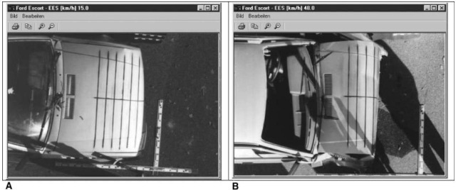
Figure 4 Vehicle damage after frontal impact at (A)15 km h \ and (B) 48kmh 1.
Where EDef defines the vehicle’s deformation energy and m the vehicle’s mass.
Thus the conservation of energy can be used in addition:
![tmp2B54_thumb[1] tmp2B54_thumb[1]](http://lh3.ggpht.com/_1wtadqGaaPs/TFBxTB72bCI/AAAAAAAALEQ/w-mVIVMtfQ0/tmp2B54_thumb1_thumb.png?imgmax=800)
where Ekini represents the kinetic energy of vehicle i before and Ekini’ after the impact.
Precrash movement
As in many cases the impact speed is not the relevant speed, precrash analyses are also of great importance. They allow determination of the drivers’ or other involved persons’ reactions. The velocities, relative positions and visibilities at the reaction point can then be investigated and the cause of the accident and the failures of the involved persons or vehicles can be identified. There are several types of failures or combinations of failures, that cause accidents: the vehicle velocity not being adapted to traffic conditions and insufficient driver attention are only just two examples. Whenever accidents are investigated, the situation has to be analyzed from the reaction point. Only thus can real cause be found.
The Driver’s Reaction
The point of reaction can be determined by various methods, depending on the accident situation. In principle, the time from the reaction to the collision position normally consist of three major phases:
• reaction time;
• lag;
• action time. Reaction time
The reaction time defines the necessary time to identify the situation, decide the kind of reaction and start the action through activation of certain muscles. It depends on many factors, like age and tiredness, and also on some which are difficult to estimate; for example, an eye blink may increase the reaction time by approximately 0.2 s. One aspect, which is also of great importance, is the visibility of the object. In cases of low contrast or small light differences, reaction time may increase dramatically. This is why so many pedestrian accidents occur at night. In addition, there is a significant difference if the resulting action has to be performed by the arms or by the legs. The greater distance between brain and leg means that an action being performed with the leg will require a significantly longer reaction time.
Typical reaction times are between 0.5 and 1.5 s.
Racing drivers are known to react during a race within a time of 0.3 s.
Lag
The lag is defined by the amount of time required by the technical system to act. There is no lag for the steering system but a lag of 0.1-0.3 s for the brake system. This lag is mainly caused by the amount of time necessary to push the brake pedal to such a level that the full brake force is applied to the wheels. One technical solution to reducing this time is the so-called ‘brake assistant’, which automatically applies the full brake force when the brake pedal is pushed very fast.
Action time
The action time defines the time when the action (mainly braking or steering) is active.
Prevention analysis
When the point of reaction has been found, so called prevention analysis must be performed. These calculations are used to determine a fictitious scenario where the accident would not have occurred. In this case, parameters like initial velocity, shorter reaction time, better visibility or higher friction on the road are varied. These analyses are used both to determine the influence of the driver’s failure and often to change the road design to prevent similar accidents.
Sample Case
The following sample case demonstrates the analysis of a vehicle-vehicle accident caused mainly by one driver overrunning a ‘stop’ sign.
The first step when simulating a new accident is the identification of all involved vehicles. Modern simulation programs to allow access various databases containing all necessary geometric and mass data.
In a second step the involved cars can be moved to the ‘average’ collision position. Here their correct overlap must be taken into account.
To define the friction conditions and drivers’ actions, so-called ‘sequences’ can be given (Fig. 5). They can be defined in a very simple and flexible way. The different steering, brake and acceleration actions can be defined by listing the actions. The values for the individual actions can then be given. The validity of one sequence can be limited by definition of a time interval or a travel distance of the vehicle’s center of gravity. The brake or acceleration forces can be given for every wheel independently. This is important to simulate wheels locked during the accident. Changes in the friction due to oil or wet areas can be defined by identifying individual areas. The corresponding friction coefficient must then be specified.
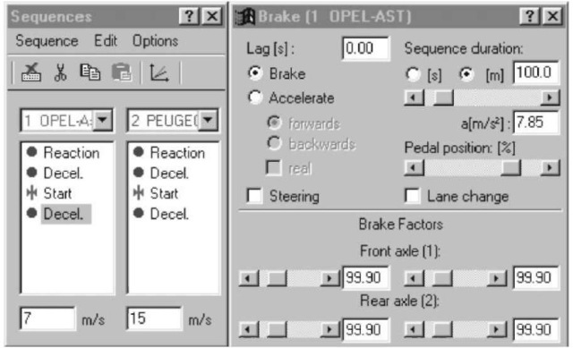
Figure 5 Definition of driver actions.
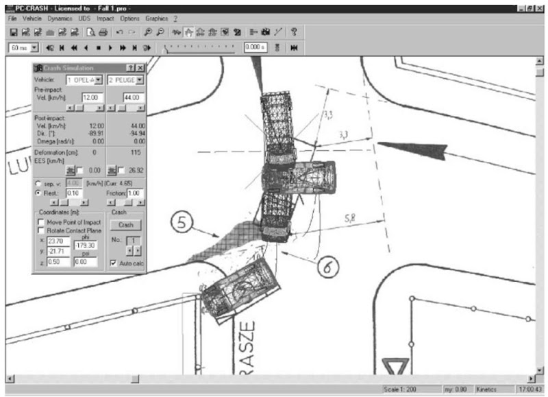
After these definitions have been given, the impact can be calculated and the postcrash movement will be simulated automatically (Fig. 6). As a result the movement of the involved vehicles, including their wheel traces, can be seen on the screen and can then be compared to a previously created DXF drawing of the scenario. As an alternative a scanned bitmap can be underlayed. So the preimpact velocities can be varied, as well as all other impact parameters. PC-CRASH, as one of the major software tools, also provides an optimization tool that allows automatic variation of specific parameters. Through the definition of target functions, the most plausible solution will be found immediately.
Figure 7 shows the movement of two vehicles after a90° impact in steps of 200 ms. A dry asphalt surfaced road was assumed.
Figure 6 Definition of impact values including results.
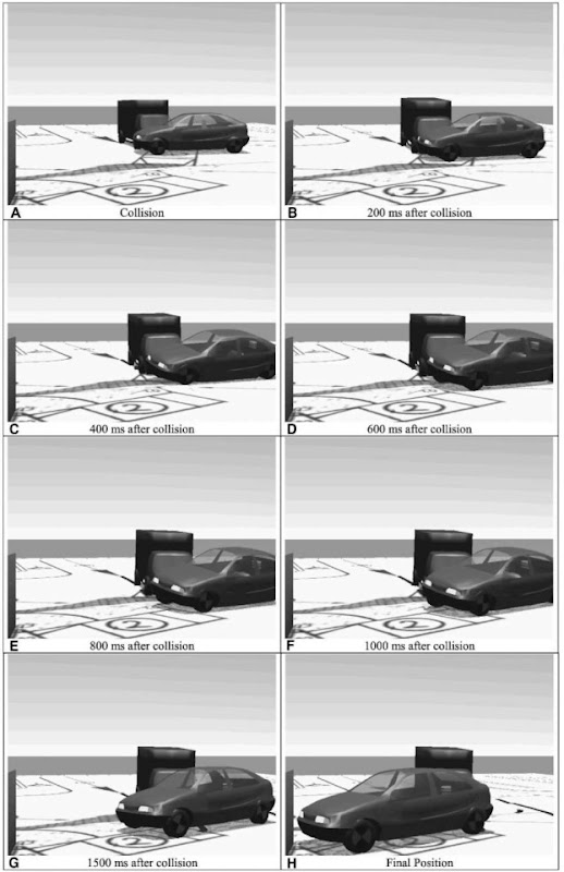
Figure 7 Vehicle movement after impact: (A) collision, (B) 200 ms, (C) 400 ms, (D) 600 ms, (E) 800 ms, (F) 1000 ms, and (G) 1500 ms after collision, (H) final position.
Results
The major fault in this case was that the driver of the private car should have stopped before the crossing. From brake traces drawn from the truck before the impact, which had a length of 7 m, the initial speed of the truck was calculated to be 60kmh-1. The truck driver reacted 1.7 s before the collision. Driving at a speed of 48 km h- 1 or less, the accident would have been prevented, as the truck would have stopped before the impact. For these calculations a reaction time of1 s and a brake lag of0.2 s was assumed. Ifthe driver of the truck had been driving at a speed of 50 km h-1, the truck would have reached the collision position 2.4 s after he had reacted. This means the private car would have continued for 0.7s and thus have passed an additional distance of approximately 2.3 m, insufficient to prevent the accident. So the accident would have also occurred at an initial speed of 50 km h-1 which was the speed limit at the reaction point but the impact speed would have been reduced from 44 km h- 1 to approximately 15 km h- 1.
