NONLINEAR OPTICAL PROPERTIES OF FIBERS
A selection of these are included in "Further Reading" at the end of this topic. We will content ourselves with an overview of the subject, and consider nonlinear effects which are most important in either limiting or enhancing the performance of fibers. To date, most of the applications of nonlinear optics in fibers are in the area of ultralong distance telecommunications.41,58-60 However, nonlinearities can limit the power-handling ability of fibers and can be an important limitation for certain medical/surgical applications.
Stimulated Scattering Processes
The low loss and long interaction length of an optical fiber makes it an ideal medium for stimulating even relatively weak scattering processes. Two important processes in fibers are: (1) stimulated Raman scattering, the interaction of the guided wave with high-frequency optical phonons in the material, and (2) stimulated Brillouin scattering, the emission, amplification, and scattering of low-frequency acoustic waves. These are distinguished by the size of the frequency shift and the dynamics of the process, but both can act to limit the power available for transmission.
Stimulated Raman scattering (SRS) produces a frequency shift of about 400 cm-1 from the incident laser line. The equation governing the power growth of the Raman-shifted mode is as follows
where PR denotes the power of the Stokes-shifted light, PP is the pump power (this is the power in the initially excited mode), and aP is the effective area of the pump. The Raman gain gR ultimately determines the SRS-limited light intensity. For typical single-mode silica fibers, gR is about 10-11 cm/W, and yields a power limit of
beyond which the guided wave power will be efficiently Raman-shifted and excess loss will begin to appear at the pump wavelength.
Stimulated Brillouin scattering (SBS) can yield an even lower stimulated scattering threshold. Acoustic waves in the fiber tend to form a Bragg index grating, and scattering occurs primarily in the backward direction. The Brillouin gain gB is much higher than Raman gain in fibers (gB = 5 x 10⁻⁹ cm/W) and leads to a stimulated scattering threshold of
for a narrowband, CW input.
Either type of stimulated scattering process can be used as a source of gain in the fiber. Injecting a signal within the frequency band of the stimulated scattering process will provide amplification of the input signal. Raman amplification tends to be the more useful of the two because of the relatively large frequency shift and the broader-gain bandwidth. SBS has been used in applications such as coherent optical communications48 where amplification of a pilot carrier is desired.
The gain bandwidth for SBS is quite narrow—100 MHz for a typical fiber. SBS is therefore only important for sources whose spectra lie within this band. An unmodulated narrow-band laser source such as would be used as a local oscillator in a coherent system would be highly susceptible to SBS, but a directly modulated laser with a 1-GHz linewidth under modulation (modulated laser linewidths can extend well into the GHz range due to frequency chirp) would have an SBS threshold about ten times that of the narrow linewidth source.
Pulse Compression and Soliton Propagation
A major accomplishment in the push toward short pulse propagation in optical fibers was the prediction and observation of solitary wave propagation. In a nonlinear dispersive medium, solitary waves may exist provided the nonlinearity and dispersion act to balance one another. In the case of soliton propagation, the nonlinearity is a refractive index which follows the pulse intensity in a nearly instantaneous fashion:
For silica fibers,
TABLE 5 Normalized Variables of the Nonlinear Schrodinger Equation
|
A |
Pulse amplitude |
|
z |
Longitudinal coordinate |
|
t |
Time |
 |
Peak power |
 |
Pulse width |
 |
 |
 |
Propagation constant |
 |
Dispersion (2d order) |
 |
To/|p2| dispersion length |
 |
Nonlinear refractive index |
 |
 |
 |
 |
 |
 |
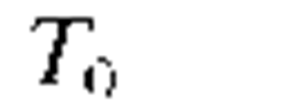
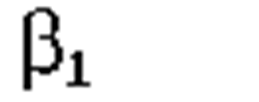
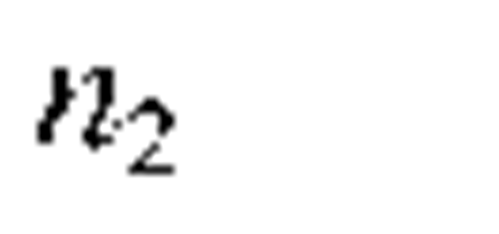
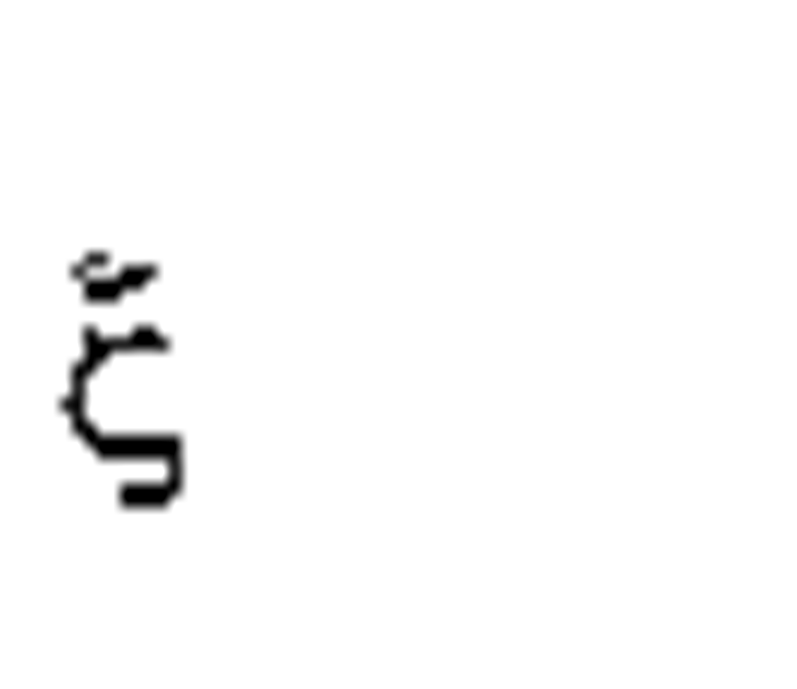
The scalar equation governing pulse propagation in such a nonlinear dispersive medium is sometimes termed the nonlinear Schrodinger equation
where the symbols are defined in Table 5. Certain solutions of this equation exist in which the pulse propagates without change in shape; these are the soliton solutions. Solitons can be excited in fibers and propagate great distances before breaking up. This is the basis for fiber-based soliton communication.
Figure 27 illustrates what happens to a pulse which propagates in such a medium. The local refractive index change produces what is commonly known as self phase modulation. Since n2 is positive, the leading edge of the pulse produces a local increase in refractive index. This results in a red shift in the instantaneous frequency. On the trailing edge, the pulse experiences a blue shift. If the channel is one which exhibits normal dispersion, the red-shifted edge will advance while the blue-shifted edge will retard, resulting in pulse spreading If, however, the fiber exhibits anomalous dispersion (beyond 1.3 |im for most single-mode fibers), the red-shifted edge will retard and the pulse will be compressed. Fibers have been used in this way as pulse compressors for some time. In the normal dispersion regime, the fiber nonlinearity is used to chirp the pulse, and a grating pair supplies the dispersion necessary for compression.
FIGURE 27 A pulse propagating through a medium with an intensity-dependent refractive index will experience frequency shifts of the leading and trailing edges of the pulse (left). Upon transmission through a fiber having anomalous dispersion, the pulse compresses (right).
In the anomalous dispersion regime, the fiber can act both to chirp and compress the pulse. Near the dispersion minimum, higher-order dependence of the group delay on wavelength becomes important, and simple pulse compression does not take place.
Pulse compression cannot continue indefinitely, since the linear dispersion will always act to spread the pulse. At a critical shape, the pulse stabilizes and will propagate without change in shape. This is the point at which a soliton forms. The lowest-order soliton will propagate entirely without change in shape, higher order solitons (which also carry higher energy) experience a periodic evolution of pulse shape.
A soliton requires a certain power level in order to maintain the necessary index change. Distortion-free pulses will therefore propagate only until the fiber loss depletes the energy. Since solitons cannot persist in a lossy channel, they were long treated merely as laboratory curiosities. This was changed by several successful demonstrations of extremely long distance soliton transmission by the inclusion of gain to balance the loss. The gain sections, which initially made use of stimulated Raman scattering, now consist of rare-earth doped fiber amplifiers. The record for repeaterless soliton transmission is constantly being challenged. At the time of this writing, distance of well over 10,000 km have been demonstrated in recirculating loop experiments.
In the laboratory, solitons have most often been generated by mode-locked laser sources. Mode-locked solid state laser sources are generally limited to low duty-cycle pulses, with repetition rates in the 1-GHz range or less. The mode-locked pulse train must then be modulated to carry data, a process which must be carried out externally. There is a high level of current interest in Erbium-doped fiber lasers as mode-locked sources for ultralong distance data communications. Despite the capability of high duty cycle, directly modulated semiconductor lasers are generally rendered unsuitable for soliton communications by the spectral broadening that occurs under modulation.
Four-Wave Mixing
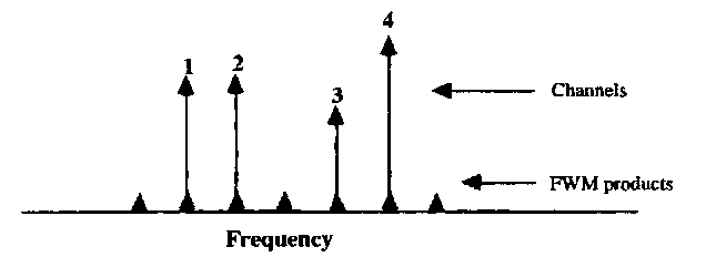
The nonlinear refractive index is simply a degenerate case of a third-order optical nonlin-earity, in which the polarization of the medium responds to the cube of the applied electric field. It is possible for widely separated frequencies to phase modulate one another via the fiber nonlinearity, generating sidebands which interfere with neighboring channels in a multiplexed system. This represents an important limit to channel capacity in either WDM or FDM systems. The simplest picture of the four-wave mixing process in fibers can be illustrated by the transmission and cross-phase modulation of four equally spaced channels shown in Fig. 28. Channels 1 and 2 interfere, producing an index of refraction which oscillates at the difference frequency. This modulation in refractive index modulates channel 4, producing sidebands at channels 3 and 5. This is only the simplest combination of frequencies. Four-wave mixing allows any combination of three frequencies beating together to produce a fourth. If the fourth frequency lies within a communication band, that channel can be rendered unusable.
FIGURE 28 The effects of four-wave mixing on multichannel transmission through an optical fiber.
This channel interference can effect either closely spaced channels, as one encounters with coherent communications, or the rather widely separated channels of a WDM system. Efficient four-wave mixing requires phase matching of the interacting waves throughout the interaction length—widely separated channels will therefore be phase matched only in a region of low-fiber dispersion.
The communications engineer will recognize this as little more than the intermodulation products which must always be dealt with in a multichannel communications system with small nonlinearities. Four-wave mixing merely produces intermodulation products over an extremely wide bandwidth. Just as with baseband nonlinearities in analog communications systems, judicious allocation of channels can minimize the problem, but at the expense of bandwidth. The cumulative effect of the nonlinearities increases with interaction length and therefore imposes an important limit on frequency or wavelength-division multiplexed systems.
Photorefractive Nonlinearities in Fibers
There also exists a class of integrating, photorefractive nonlinearities in optical fibers which have been of some interest in recent years. We use the word photorefractive loosely here, simply to indicate a long-term change in either the first- or second-order susceptibility with light exposure. The effects appear strongest in fibers with a germania content, but the precise role of the glass constituents in these processes is still an area of active research.
Bragg Index Gratings. Photons of energy near a UV absorption edge can often write permanent phase gratings by photoionizing certain constituents or impurities in the material. This is the case for LiNbO4 and certain other ferroelectric materials, and such effects have also been observed in germania-silica fibers. The effects were first observed in the process of guiding relatively high power densities of green light—it was found that a high backscatter developed over a period of prolonged exposure. The fiber then exhibited the transmission characteristics of a Bragg grating, with extremely high resonant reflectivities.
The writing of permanent gratings in fibers using UV exposure is now relatively commonplace. Bragg gratings can be used as filters in WDM systems, reflectors on fiber lasers, and possibly optical switches. For short lengths, the gratings are most easily formed holographi-cally, by using two interfering beams from a pulsed UV source such as an excimer laser. The fiber is exposed from the side; by controlling the angle of the two interfering beams, any grating period may be chosen.
Frequency Doubling in Germania-Silica Fibers. While it is not surprising that UV exposure could produce refractive index changes, a rather unexpected discovery was the fact that strong optical fields inside the fiber could produce a second-order susceptibility, resulting in efficient frequency doubling. Electro-optic effects such as frequency doubling require that a crystalline material lack a center of symmetry while an amorphous material must lack a statistical center of symmetry. It has long been known that certain materials will develop an electro-optic effect under a suitable applied field. This process, known as poling, provides the necessary microscopic alignment of dipoles for development of the nonlinear susceptibility. In optical fibers, a type of self-poling occurs from the strong fundamental beam, resulting in a second-order susceptibility and efficient frequency doubling.
Efficient frequency doubling requires both a noncentrosymmetric material and adequate phase matching between the fundamental and second harmonic waves. The mechanism by which the fiber is both poled and phase matched is still not fully understood at the time of this writing, and it remains to be seen whether this represents an exciting, new application of germania-silica fibers or simply an internal damage mechanism which limits the ultimate power delivery of the fiber.
OPTICAL FIBER MATERIALS: CHEMISTRY AND FABRICATION
What is arguably the most important breakthrough in the history of optical fiber technology occurred in the materials development. Until 1970, many scientists felt that glasses of moderate softening points and smooth phase transitions would allow for easier drawing and better control. The choice of Corning Glass Works (now Corning, Inc.) to go to (what was then) the somewhat more difficult chemistry of the nearly pure silica fiber allowed both a dramatic reduction in fiber attenuation and a better understanding of the role of the chemical constituents in fiber loss. Researchers soon found that the best dopants for altering the refractive index were those which provided a weak index change without providing a large shift in the UV absorption edge. Conventional fiber chemistry consists of dopants such as GeO2, P2O5 (for raising the refractive index) and B2O3 or SiF4 (for lowering the refractive index).
Silica has both UV and mid-IR absorption bands; these two bands result in a fundamental limit to the attenuation which one can achieve in the silica system. This occurs despite the fact that the Rayleigh scattering contribution decreases as X-4, and the ultraviolet Urbach absorption edge decreases even faster with increasing X. The infrared absorption increases with long wavelengths, and becomes dominant beyond wavelengths of about 1.6 |im, resulting in a fundamental loss minimum near 1.55 |im.
The promise of achieving a lower Rayleigh scattering limit in the mid-infrared (as well as the possible applications of fiber to the CO2 laser wavelength range) have spurred a great deal of research in fiber materials which exhibit better infrared transparency. Two important representative materials are the heavy-metal fluoride glasses and the chalcogenide glasses. While both classes exhibit better infrared transparency, neither has yet improved to the point of serious competition with silica materials.
For a number of years, attenuation in optical fibers was limited by a strong absorption band near X = 1.4 |im. (An examination of attenuation curves of early telecommunications-grade fiber shows it nearly unusable at what are now the wavelengths of prime interest— 1.3 |im and 1.55 |im.) This absorption, which was linked to the presence of residual OH ions, grew steadily lower with the improvement of fiber fabrication techniques until the loss minimum at X = 1.55 |im was eventually brought close to the Rayleigh scattering limit.
The low-cost, low-temperature processes by which polymers can be fabricated has led to continued research into the applications of plastic fiber to technologies which require low cost, easy connectivity, and that are not loss-limited. The additional flexibility of these materials makes them attractive for large-core, short-length applications in which one wishes to maximize the light insertion. Hybrid polymer cladding-silica core fibers have also received some attention in applications requiring additional flexibility.
The final triumph of fiber chemistry in recent years has been the introduction and successful demonstration of extremely long distance repeaterless fiber links using rare-earth doped fiber amplifiers. This represented the climax of a long period of research in rare-earth doped glasses which went largely unnoticed by the optics community. As a result, there has been an explosion of work in the materials science, materials engineering, and applications of rare-earth doped optical fibers.
Fabrication of Conventional Optical Fibers
Conventional fabrication of low-loss optical fibers requires two stages. The desired refractive index profile is first fabricated in macroscopic dimensions in a preform. A typical preform is several centimeters in width and a meter in length, maintaining the dimensions and dopant distribution in the core and cladding that will eventually form in the fiber.
Chemical vapor deposition (CVD) is the primary technology used in fiber manufacturing. The fabrication process must satisfy two requirements: (1) high purity, and (2) precise control over composition (hence, refractive index) profiles. Manufacturing considerations favor approaches which provide a fast deposition rate and comparatively large preforms. In CVD processes, submicron silica particles are produced through one (or both) of the following chemical reactions
The reactions are carried out at a temperature of about 1800°C. The deposition leads to a high-purity silica soot which must then be sintered in order to form optical quality glass.
Modern manufacturing techniques, generally speaking, use one of two processes.61 In the so-called "inside process," a rotating silica substrate tube is subjected to an internal flow of reactive gases. The two inside processes which have received the most attention are modified chemical vapor deposition (MCVD) and plasma-assisted chemical vapor deposition (PCVD). Both techniques require a layer-by-layer deposition, controlling the composition at each step in order to reach the correct target refractive index. Oxygen, as a carrier gas, is bubbled through SiCl4, which has a relatively high vapor pressure at room temperature.
The PCVD process provides the necessary energy for the chemical reaction by direct RF plasma excitation. The submicron-sized particles form on the inner layer of the substrate, and the composition of the layer is controlled strictly by the composition of the gas. PCVD does not require the careful thermal control of other methods, but requires a separate sintering step to provide a pore-free preform. A final heating to 2150°C collapses the preform into a state in which it is ready to be drawn.
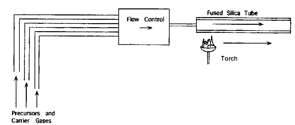
The MCVD process (Fig. 29) accomplishes the deposition by an external, local application of a torch. The torch has the dual role of providing the necessary energy for oxidation and the heat necessary for sintering the deposited SiO2. The submicron particles are deposited on the "leading edge" of the torch; as the torch moves over these particles, they are sintered into a vitreous, pore-free layer. Multiple passes result in a layered, glassy deposit which should approximate the target radial profile of the fiber. As with PCVD, a final pass is necessary for collapse of the preform before the fiber is ready to be drawn. MCVD requires rather precise control over the temperature gradients in the tube but has the advantage of accomplishing the deposition and sintering in a single step.
In the "outside process," a rotating, thin cylindrical target (or mandrel) is used as the substrate for a subsequent chemical vapor deposition, and requires removal before the boule is sintered. Much of the control in these deposition techniques lies in the construction of the torch. For an outside process, the torch supplies both the chemical constituents and the heat for the reaction.
FIGURE 29 The modified chemical vapor deposition (MCVD) process for preform fabrication.
FIGURE 30 Outside method of preform fabrication. The soot deposition (a) is followed by sintering (b) to cast the preform.
Two outside processes which have been used a great deal are the outside vapor deposition (OVD) and the vapor axial deposition (VAD) techniques. Figure 30 illustrates a generic outside process. In the OVD process the torch consists of discrete holes formed in a pattern of concentric rings. The primary chemical stream is at the center, followed by O2 (acting as a shield gas), premixed methane/oxygen, and another shield ring. The torch itself translates along the rotating boule and the dopants are dynamically controlled to achieve the necessary profiling.
The VAD torch is comprised of a set of concentric annular apertures, with a chemical sequence similar to the OVD. In contrast to the OVD method, the VAD torch is held stationary during the deposition; the rotating target is held vertically, and is lifted as the deposition continues.
Dopant Chemistry
Standard dopants for silica fiber include GeO2, P2O5, B2O3, and SiF4. The former two are used to increase the refractive index (and are therefore used in the core), while the latter decrease the index of refraction (and are therefore used in the cladding). The CVD processes will often use oxygen as a carrier gas with the high vapor pressure liquids GeCLi, POCl3, or SiF4. The reaction which produces the dopant "soot" is then
As noted in a recent article by Morse et al.,62 "Nature has been kind in the creation of the high vapor pressure liquid precursors used in the fabrication of optical fibers for the transmission of telecommunication signals." This has been an extremely important factor in the success of CVD fiber fabrication techniques. The problem of introducing more exotic dopants, such as the rare-earth elements, is not quite so straightforward and there does not appear to exist, at this time, a single, widely used technique. The problem of control over the rare-earth dopant profile is compounded by the fact that research in laser and amplifier design is ongoing, and the optimum dopant profile for rare-earth doped fibers and amplifiers is, in many cases, still unknown. Despite these uncertainties, rare-earth doped fibers have already been introduced into commercial products and promise to spearhead the next generation of long distance telecommunications systems.
Other Fabrication Techniques
There are other preform fabrication and fiber drawing techniques. These are not generally used in telecommunications-grade silica fiber, but can be of advantage for glass chemistries which do not easily lend themselves to chemical vapor deposition. Several examples of this will be described in the following section on infrared fiber fabrication.
CVD materials, while the most popular, are not the only methods for preform fabrication. Alternative methods of preform fabrication include both bulk casting and a class of non-CVD tubular casting techniques. One such technique is the "rod-in-tube" method, in which the core and cladding materials are cast separately and combined in a final melting/collapsing step. This method assures a homogeneous, low-impurity content core but risks introducing defects and bubbles into the core/cladding interface.
The most well-known method of preform-free drawing is the double crucible method, in which the core and cladding melts are formed separately and combined in the drawing process itself. This eliminates the need for a very large preform in the case of long lengths of fiber. The index profile is established in the drawing process itself, and index gradients are therefore difficult to establish unless additional crucibles are added. Another difficulty of the crucible method is the sometimes inadequate control of the concentricity of the core and cladding.
Infrared Fiber Fabrication
The major applications of interest for infrared optical fibers are as follows:
1. Ultra-low-loss communication links
2. CO2 laser transmission for medical applications
3. Thermal imaging and remote temperature monitoring
4. Gas sensing
These may differ rather dramatically in their attenuation requirements and spectral region of interest. For example, an ultra-low-loss communications link requires attenuation somewhat less than 0.1 dB/km in order to be competitive with silica fiber. Typical medical applications simply require high-power handling capabilities of a CO2 laser over meter lengths. All of these applications require a departure from the silica-based chemistry which has been so successful for applications in the near infrared and visible. Much of the generic chemistry of these glasses is covered in Chap. 33 of Vol. II, "Crystals and glasses." Our intent here is to give an overview of the fiber types and the general state of the materials technology in each case.
Chalcogenide Fibers. Sulfide, selenide, and telluride glasses have all been used for bulk infrared optics—particularly for applications involving CO2 (X= 10.6 |im) or CO laser transmission (X = 5.4 |im). Infrared fibers have been drawn from these materials and yielded trans mission losses of the order of 1 dB/meter in the 5- to 7-|im region.63 The preform fabrication and drawing of chalcogenide fibers is much more difficult than that of silica due primarily to its sensitivity both to oxygen and moisture. Both oxidation and crystallization can occur at the temperatures necessary to draw the fiber. Either will result in catastrophically high losses and fiber weakness.
Fluoride Fibers. Fluoride fibers have received the most attention for low-loss telecommunications applications, because the theoretical limit for Rayleigh scattering is considerably lower. This is due both to a higher-energy UV absorption edge and better infrared transparency. The difficulty is that excess absorption has proven rather difficult to reduce, and the lowest published losses to date have been near 1 dB/km for long fiber lengths.64,65 The state-of-the-art in fluoride fiber fabrication is still well above the Rayleigh scattering limit but does show the expected improvement over silica fiber in wavelengths beyond 1.6 |im. Fabrication of very short fiber lengths has been somewhat more successful, with reported losses as low as 0.025 dB/km at 2.55 |im.66
The residual loss for longer fibers has been largely linked to extrinsic impurity/defect content. Recent articles by Takahashi and Sanghera64,65 have noted the role of transition metal and rare-earth ions, submicron platinum particles, oxyfluoride particles, fluoride microcrys-tals, and bubbles as both extrinsic absorbers and scatterers. The defects of interest originate from a variety of sources, and there has been much discussion on which defects dominate the scattering process. To date, the consensus appears to be that impurity absorption does not adequately account for the current loss limits, but does account for residual losses in the neighborhood of 0.2 dB/km.
The classes of defects which have been blamed for the current loss limits are as follows:
Platinum particles. These arise from the use of platinum crucibles. The use of vitreous carbon crucibles eases this contamination.
Core bubbles. This is clearly a problem in the preform fabrication and appears in some of the bulk casting techniques.
Interfacial bubbles. Bubbles appearing at the core-cladding interface have been named as being a major cause of excess scattering. These appear to be a particular problem for those techniques which employ separate core and cladding melts. This unfortunately negates some of the advantages offered by the crucible techniques in fluoride fiber fabrication.
Fluoride microcrystals. Crystals can nucleate at a variety of defect sites. Many of these sites appear at the core-cladding interface, producing interface roughness and scattering. Since, for step-index fibers, the integrity of the core-cladding interface is essential to the confinement of the optical wave, a small amount of interface roughness can produce rather high excess losses.
This class of compositions has received the designation ZBLAN, after its heavy-metal constituents. The large number of components makes it immediately obvious that both phase separation and crystallization are important issues in fabrication. Either can produce catastrophic increases in loss as well as mechanical weakening of the fiber, and it is clear that many materials science challenges remain in the area of fluoride fiber fabrication.
![tmp8-129_thumb[2][2][2][2][2] tmp8-129_thumb[2][2][2][2][2]](http://what-when-how.com/wp-content/uploads/2011/09/tmp8129_thumb22222_thumb.png)
![tmp8-130_thumb[2][2][2][2][2] tmp8-130_thumb[2][2][2][2][2]](http://what-when-how.com/wp-content/uploads/2011/09/tmp8130_thumb22222_thumb.png)
![tmp8-131_thumb[2][2][2][2][2] tmp8-131_thumb[2][2][2][2][2]](http://what-when-how.com/wp-content/uploads/2011/09/tmp8131_thumb22222_thumb.png)
![tmp8-148_thumb[2][2][2][2][2] tmp8-148_thumb[2][2][2][2][2]](http://what-when-how.com/wp-content/uploads/2011/09/tmp8148_thumb22222_thumb.png)

![tmp8-151_thumb[2][2][2][2][2] tmp8-151_thumb[2][2][2][2][2]](http://what-when-how.com/wp-content/uploads/2011/09/tmp8151_thumb22222_thumb.png)

![tmp8-154_thumb[2][2][2][2][2] tmp8-154_thumb[2][2][2][2][2]](http://what-when-how.com/wp-content/uploads/2011/09/tmp8154_thumb22222_thumb.png)
