Application to Face Recognition Under Varying Illumination
Qing et al. [44] used the face relighting technique as described in the previous section for face recognition under different lighting environments. For any given face image under unknown illumination, they first applied the face relighting technique to generate a new image of the face under canonical illumination. Canonical illumination is the constant component of the spherical harmonics, which can be obtained by keeping only the constant coefficient (x00 in (20.7)) while setting the rest of the coefficients to zero. The ratio-image technique of (20.8) is used to generate the new image under canonical illumination.
Image matching is performed on the images under canonical illumination. Qing et al. [44] performed face recognition experiments with the PIE database [51]. They reported significant improvement of the recognition rate after using face relighting. The reader is referred to their article [44] for detailed experimental results.
Facial Expression Synthesis
In the past several years, facial expression synthesis has been an active research topic [7, 11, 24, 29, 35, 54, 56, 66]. Generally face expression synthesis techniques can be divided into three categories: physically based facial expression synthesis, morph-based facial expression synthesis, and expression mapping (also called performance-driven animation).
Physically Based Facial Expression Synthesis
One of the early physically based approaches is the work by Badler and Platt [2], who used a mass and spring model to simulate the skin. They introduced a set of muscles. Each muscle is attached to a number of vertices of the skin mesh. When the muscle contracts, it generates forces on the skin vertices, thereby deforming the skin mesh. A user generates facial expressions by controlling the muscle actions.
Waters [58] introduced two types of muscles: linear and sphincter. The lips and eye regions are better modeled by the sphincter muscles. To gain better control, they defined an influence zone for each muscle so the influence of a muscle diminishes as the vertices are farther away from the muscle attachment point.
Terzopoulos and Waters [55] extended Waters’ model by introducing a three-layer facial tissue model. A fatty tissue layer is inserted between the muscle and the skin, providing more fine grain control over the skin deformation. This model was used by Lee et al. [25] to animate Cyberware scanned face meshes.
One problem with the physically based approaches is that it is difficult to generate natural looking facial expressions. There are many subtle skin movement, such as wrinkles and furrows, that are difficult to model with a mass-and-spring scheme.
Morph-Based Facial Expression Synthesis
Given a set of 2D or 3D expressions, one could blend these expressions to generate new expressions. This technique is called morphing or interpolation. This technique was first reported in Parke’s pioneer work [40]. Beier and Neely [4] developed a feature-based image morphing technique to blend 2D images of facial expressions. Bregler et al. [6] applied the morphing technique to mouth regions to generate lip-synch animations.
Pighin et al. [42] used the morphing technique on both the 3D meshes and texture images to generate 3D photorealistic facial expressions. They first used a multiview stereo technique to construct a set of 3D facial expression examples for a given person. Then they used the convex linear combination of the examples to generate new facial expressions. To gain local control, they allowed the user to specify an active region so the blending affects only the specified region. The advantage of this technique is that it generates 3D photorealistic facial expressions. The disadvantage is that the possible expressions this technique can generate is limited. The local control mechanism greatly enlarges the expression space, but it puts burdens on the user. The artifacts around the region boundaries may occur if the regions are not selected properly. Joshi et al. [22] developed a technique to automatically divide the face into subregions for local control. The region segmentation is based on the analysis of motion patterns for a set of example expressions.
Expression Mapping
Expression mapping (also called performance-driven animation) has been a popular technique for generating realistic facial expressions. This technique applies to both 2D and 3D cases. Given an image of a person’s neutral face and another image of the same person’s face with an expression, the positions of the face features (e.g., eyes, eyebrows, mouths) on both images are located either manually or through some automatic method. The difference vector of the feature point positions is then added to a new face’s feature positions to generate the new expression for that face through geometry-controlled image warping (we call it geometric warping) [4, 30, 61]. In the 3D case, the expressions are meshes, and the vertex positions are 3D vectors. Instead of image warping, one needs a mesh deformation procedure to deform the meshes based on the feature point motions [16].
Williams [60] developed a system to track the dots on a performer’s face and map the motions to the target model. Litwinowicz and Williams [30] used this technique to animate images of cats and other creatures.
Because of its simplicity, the expression mapping technique has been widely used in practice. One great example is the FaceStation system developed by Eye-matic [19]. The system automatically tracks a person’s facial features and maps his or her expression to the 3D model on the screen. It works in real time without any markers.
There has been much research done to improve the basic expression mapping technique. Pighin et al. [42] parameterized each person’s expression space as a convex combination of a few basis expressions and proposed mapping one person’s expression coefficients to those of another person. It requires that the two people have the same number of basis expressions and that there is a correspondence between the two basis sets. This technique was extended by Pyun et al. [43]. Instead of using convex combination, Pyun et al. [43] proposed to the use of radial basis functions to parameterize the expression space.
Noh and Neumann [39] developed a technique to automatically find a correspondence between two face meshes based on a small number of user-specified correspondences. They also developed a new motion mapping technique. Instead of directly mapping the vertex difference, this technique adjusts both the direction and the magnitude of the motion vector based on the local geometries of the source and target model.
Mapping Expression Details
Liu et al. [33] proposed a technique to map one person’s facial expression details to a different person. Facial expression details are subtle changes in illumination and appearance due to skin deformations. The expression details are important visual cues, but they are difficult to model and synthesize. Given a person’s neutral face image and an expression image, Liu et al. [33] observed that the illumination changes caused by the skin deformations can be extracted in a skin color independent manner using an expression ratio image (ERI). The ERI can then be applied to a different person’s face image to generate the correct illumination changes caused by the skin deformation of that person’s face.
Let Ia be person A’s neutral face image, let![]() be A’s expression image. Given a point on the face, let pa be its albedo, and let n be its normal on the neutral face. Let n’ be the normal when the face makes the expression. By assuming Lambertian model, we have
be A’s expression image. Given a point on the face, let pa be its albedo, and let n be its normal on the neutral face. Let n’ be the normal when the face makes the expression. By assuming Lambertian model, we have![]() Taking the ratio, we have:
Taking the ratio, we have:
Note that![]() captures the illumination changes due to the changes in the surface normals; furthermore, it is independent of A’s albedo.
captures the illumination changes due to the changes in the surface normals; furthermore, it is independent of A’s albedo.![]() is called the expression ratio image. Let
is called the expression ratio image. Let![]() be person B’s neutral face image. Let pb be its albedo. By assuming that B and A have similar surface normals on their corresponding points, we have
be person B’s neutral face image. Let pb be its albedo. By assuming that B and A have similar surface normals on their corresponding points, we have![]() Let
Let![]() be the image of B making the same expression as A; then
be the image of B making the same expression as A; then
and so
Therefore, we can compute![]() by multiplying Ib with the expression radio image.
by multiplying Ib with the expression radio image.
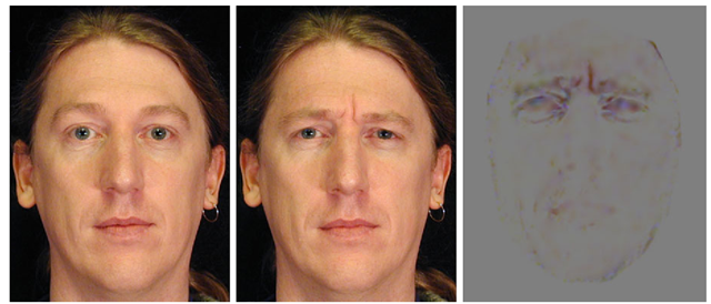
Fig. 20.9 Expression ratio image. Left: neutral face. Middle: expression face. Right: expression Ratio image. The ratios of the RGB components are converted to colors for display purpose.
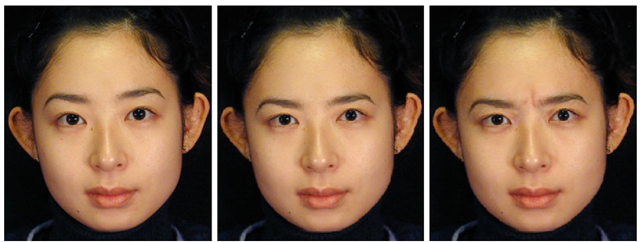
Fig. 20.10 Mapping a thinking expression. Left: neutral face. Middle: result from geometric warping. Right: result from ERI.
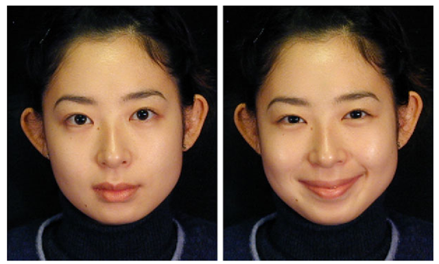
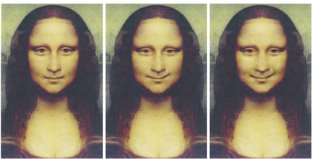
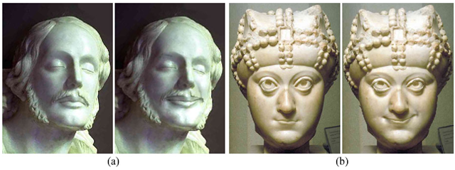
Figure 20.9 shows a male subject’s thinking expression and the corresponding ERI. Figure 20.10 shows the result of mapping the thinking expression to a female subject. The image in the middle is the result of using traditional expression mapping. The image on the right is the result generated using the ERI technique. We can see that the wrinkles due to skin deformations between the eyebrows are mapped well to the female subject. The resulting expression is more convincing than the result from the traditional geometric warping. Figure 20.12 shows the result of mapping the smile expression (Fig. 20.11) to Mona Lisa. Figure 20.13 shows the result of mapping the smile expression to two statues.
Geometry-Driven Expression Synthesis
One drawback of the ERI technique is that it requires the expression ratio image from the performer. Zhang et al. [65] proposed a technique that requires only the feature point motions from the performer, as for traditional expression mapping.
Fig. 20.11 Smile expression used to map to other people’s faces
Fig. 20.12 Mapping a smile to Mona Lisa’s face. Left: “neutral” face. Middle: result from geometric warping. Right: result from ERI.
Fig. 20.13 Mapping expressions to statues. a Left: original statue. Right: result from ERI. b Left: another statue. Right: result from ERI.
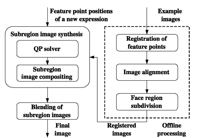
Fig. 20.14 Geometry-driven expression synthesis system.
One first computes the desired feature point positions (geometry) for the target model, as for traditional expression mapping. Based on the desired feature point positions, the expression details for the target model are synthesized from examples.
Let![]() be the example expressions where Gi represents the geometry and Ii is the texture image (assuming that all the texture images Ii are pixel aligned). Let
be the example expressions where Gi represents the geometry and Ii is the texture image (assuming that all the texture images Ii are pixel aligned). Let![tmp7527421_thumb[2] tmp7527421_thumb[2]](http://what-when-how.com/wp-content/uploads/2012/06/tmp7527421_thumb2_thumb.png) be the set of all possible convex combinations of these examples. Then
be the set of all possible convex combinations of these examples. Then
Note that each expression in the space![]() has a geometric component
has a geometric component![tmp7527426_thumb[2] tmp7527426_thumb[2]](http://what-when-how.com/wp-content/uploads/2012/06/tmp7527426_thumb2_thumb.png) and a texture component
and a texture component![tmp7527427_thumb[2] tmp7527427_thumb[2]](http://what-when-how.com/wp-content/uploads/2012/06/tmp7527427_thumb2_thumb.png) Because the geometric component is much easier to obtain than the texture component, Zhang et al. [65] proposed using the geometric component to infer the texture component. Given the geometric component G, one can project G to the convex hull spanned by
Because the geometric component is much easier to obtain than the texture component, Zhang et al. [65] proposed using the geometric component to infer the texture component. Given the geometric component G, one can project G to the convex hull spanned by![]() and then use the resulting coefficients to composite the example images and obtain the desired texture image.
and then use the resulting coefficients to composite the example images and obtain the desired texture image.
To increase the space of all possible expressions, they proposed subdividing the face into a number of subregions. For each subregion, they used the geometry associated with this subregion to compute the subregion texture image. The final expression is then obtained by blending these subregion images together. Figure 20.14 is an overview of their system. It consists of an offline processing unit and a run time unit. The example images are processed offline only once. At run time, the system takes as input the feature point positions of a new expression. For each sub-region, they solve the quadratic programming problem of (20.12) using the interior point method. They then composite the example images in this subregion together to obtain the subregion image. Finally, they blend the subregion images together to produce the expression image.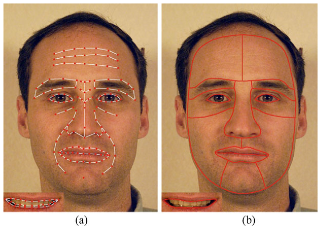
Fig. 20.15 a Feature points. b Face region subdivision.
Figure 20.15a shows the feature points they used by Zhang et al. [65]. Figure 20.15b shows the face region subdivision. From Fig. 20.15a, we can see that the number of feature points used for their synthesis system is large. The reason is that more feature points are better for the image alignment and for the quadratic programming solver. The problem is that some feature points, such as those on the forehead, are quite difficult to obtain from the performer, and they are person-dependent. Thus these feature points are not suited for expression mapping. To address this problem, they developed a motion propagation technique to infer feature point motions from a subset. Their basic idea was to learn how the rest of the feature points move from the examples. To have fine-grain control, they divided the face feature points into hierarchies and performed hierarchical principal component analysis on the example expressions.
There are three hierarchies. At hierarchy 0, they used a single feature point set that controls the global movement of the entire face. There are four feature point sets at hierarchy 1, each controlling the local movement of facial feature regions (left eye region, right eye region, nose region, mouth region). Each feature point set at hierarchy 2 controls details of the face regions, such as eyelid shape, lip line shape, and so on. There are 16 feature point sets at hierarchy 2. Some facial feature points belong to several sets at different hierarchies, and they are used as bridges between global and local movement of the face, so the vertex movements can be propagated from one hierarchy to another.
For each feature point set, Zhang et al. [65] computed the displacement of all the vertices belonging to this feature set for each example expression. They then performed principal component analysis on the vertex displacement vectors corresponding to the example expressions and generated a lower dimensional vector space. The hierarchical principal component analysis results are then used to propagate vertex motions so that from the movement of a subset of feature points one can infer the most reasonable movement for the rest of the feature points.
Let![]() denote all the feature points on the face. Let
denote all the feature points on the face. Let![]() denote the displacement vector of all the feature points. For any given
denote the displacement vector of all the feature points. For any given![]() and a feature point set F (the set of indexes of the feature points belonging to this feature point set), let
and a feature point set F (the set of indexes of the feature points belonging to this feature point set), let![tmp7527437_thumb[2] tmp7527437_thumb[2]](http://what-when-how.com/wp-content/uploads/2012/06/tmp7527437_thumb2_thumb.png) denote the subvector of those vertices that belong to F. Let
denote the subvector of those vertices that belong to F. Let![]() denote the projection of
denote the projection of![]() into the subspace spanned by the principal components corresponding to F .In other words,
into the subspace spanned by the principal components corresponding to F .In other words,![]() is the best approximation of
is the best approximation of![]() in the expression subspace. Given
in the expression subspace. Given![]() let us say that
let us say that![]() is updated by
is updated by![]() if for each vertex that belongs to F its displacement in
if for each vertex that belongs to F its displacement in![]() has been replaced with its corresponding value in
has been replaced with its corresponding value in![]()
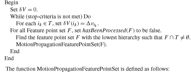
The motion propagation algorithm takes as input the displacement vector for a subset of the feature points, say,![]()
Below is a description of the motion propagation algorithm.
MotionPropagation
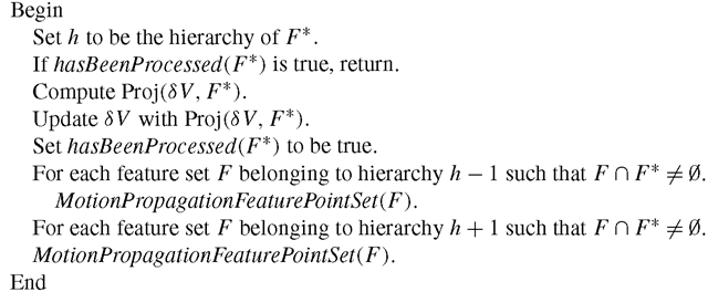
MotionPropagationFeaturePointSet(F *)
The algorithm initializes SV to a zero vector. At the first iteration, it sets SV(Ik) to be equal to the input displacement vector for vertex vik. Then it finds the feature point set with the lowest hierarchy so it intersects with the input feature point set T and calls MotionPropagationFeaturePointSet. The function uses principal component analysis to infer the motions for the rest of the vertices in this feature point set. It then recursively calls MotionPropagationFeaturePointSet on other feature point sets. At the end of the first iteration, SV contains the inferred displacement vectors for all the feature points.
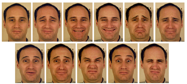
Fig. 20.16 Example images of the male subject.
Note that for the vertex in T its inferred displacement vector may be different from the input displacement vector because of the principal component projection. At the second iteration,![tmp7527465_thumb[2] tmp7527465_thumb[2]](http://what-when-how.com/wp-content/uploads/2012/06/tmp7527465_thumb2_thumb.png) is reset to the input displacement vector for all
is reset to the input displacement vector for all![]() The process repeats.
The process repeats.
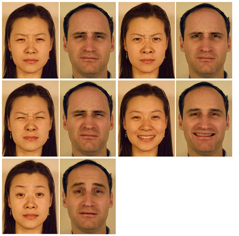
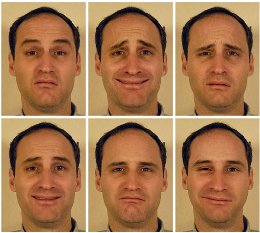
Figure 20.16 shows example images of a male subject, and Fig. 20.17 shows the results of mapping a female subject’s expressions to this male subject.
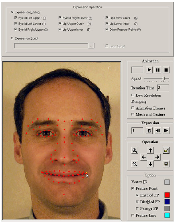
In addition to expression mapping, Zhang et al. [65] applied their techniques to expression editing. They developed an interactive expression editing system that allows a user to drag a face feature point, and the system interactively displays the resulting image with expression details. Figure 20.18 is a snapshot of their interface. The red dots are the feature points that the user can click and drag. Figure 20.19 shows some of expressions generated by the expression editing system.
Discussion
We have reviewed recent advances on face synthesis including face modeling, face relighting, and facial expression synthesis. There are many open problems that remain to be solved.
One problem is how to generate face models with fine geometric details. As discussed in Sect. 20.2, many 3D face modeling techniques use some type of model space to constrain the search, thereby improving the robustness. The resulting face models in general do not have the geometric details, such as creases and wrinkles. Geometric details are important visual cues for human perception. With geometric details, the models look more realistic; and for personalized face models, they look more recognizable to human users. Geometric details can potentially improve computer face recognition performance as well.
Another problem is how to handle non-Lambertian reflections. The reflection of human face skin is approximately specular when the angle between the view direction and lighting direction is close to 90°. Therefore, given any face image, it is likely that there are some points on the face whose reflection is not Lambertian. It is desirable to identify the non-Lambertian reflections and use different techniques for them during relighting.
Fig. 20.17 Results of the enhanced expression mapping. The expressions of the female subject are mapped to the male subject.
How to handle facial expressions in face modeling and face relighting is another interesting problem. Can we reconstruct 3D face models from expression images? One would need a way to identify and undo the skin deformations caused by the expression. To apply face relighting techniques on expression face images, we would need to know the 3D geometry of the expression face to generate correct illumination for the areas with strong deformations.
One ultimate goal in face animation research is to be able to create face models that look and move just like a real human character. Not only do we need to synthe-size facial expression, we also need to synthesize the head gestures, eye gazes, hair, and the movements of lips, teeth, and tongue.
Fig. 20.18 The expression editing interface. The red dots are the feature points which a user can click on and drag.
Fig. 20.19 Expressions generated by the expression editing system.
Face synthesis techniques can be potentially used for face detection and face recognition to handle different head poses, different lighting conditions, and different facial expressions. As we discussed earlier, some researchers have started applying some face synthesis techniques to face recognition [44, 48]. We believe that there are many more opportunities along this line, and that it is a direction worth exploring.
![tmp7527397_thumb[2] tmp7527397_thumb[2]](http://what-when-how.com/wp-content/uploads/2012/06/tmp7527397_thumb2_thumb.png)
![tmp7527403_thumb[2] tmp7527403_thumb[2]](http://what-when-how.com/wp-content/uploads/2012/06/tmp7527403_thumb2_thumb.png)
![tmp7527410_thumb[2] tmp7527410_thumb[2]](http://what-when-how.com/wp-content/uploads/2012/06/tmp7527410_thumb2_thumb.png)
![tmp7527411_thumb[2] tmp7527411_thumb[2]](http://what-when-how.com/wp-content/uploads/2012/06/tmp7527411_thumb2_thumb.png)
![tmp7527424_thumb[2] tmp7527424_thumb[2]](http://what-when-how.com/wp-content/uploads/2012/06/tmp7527424_thumb2_thumb.png)
