ABSTRACT
Planar Solid Oxide Fuel Cells (SOFCs) are composed of repeating cathode-electrolyte-anode units separated by electrically conductive interconnects. With the reduction in fuel cell operating temperature to approximately 800°C, it has become possible to use chromium-based, ferritic stainless steel or Crofer for interconnects. These interconnects must survive the high temperature oxidizing and reducing environments while maintaining electrical conductivity. Unfortunately the formation of chromium oxide scale poisons the cell by significantly reducing cathodic activity. Chromium scale formation can be inhibited by applying an electrically conductive manganese cobalt oxide (MCO) spinel coating to the interconnect prior to its installation in the fuel cell. The most cost-effective way to apply protective coatings to interconnects involves spray coating. To investigate the quality of the coatings and the coating adhesion, four-point bend experiments were undertaken at room temperature. Tensile cracking patterns on the convex surfaces of the bend specimens were used to determine the interfacial shear strengths of the coatings. SEM images of the cracked coating surfaces were processed to analyze the interface failure mechanisms, the crack spacing, and areas that spalled at higher strains. These investigations were able to show distinct differences between coatings formed with different processes parameters.
Introduction
With high efficiencies and harmless by-products, planar SOFCs have the potential to radically alter the production and distribution of electricity. Although SOFCs operate at temperatures of 700-850°C, SOFCs have several advantages over other fuel cell types. The principal advantage is fuel flexibility. Because the ceramic membrane is an oxygen ion conductor, oxygen partial pressure gradients create the voltage that allows cell operation. Thus both H2and CO can be consumed as fuel, allowing a range of reformed hydrocarbon fuels to be considered. The high operating temperatures create advantages both by enabling catalysis of the fuels without special, expensive materials and by paving the way to enhanced efficiency within combined cycle systems (e.g.,[1]). Another important advantage is the enhanced tolerance of SOFCs to fuel impurities. CO, which poisons proton exchange membrane (PEM) fuel cells, is a fuel for SOFCs. H2S, another common contaminant in hydrocarbon and some biomass-derived hydrogen fuels, is tolerated in SOFCs currently being developed; competing fuel cell systems require large desulfurizers which reduces overall system efficiency. SOFCs are not without their own challenges, however. In particular, SOFC materials selection, cell and stack design, manufacturing, conditioning, sealing, and degradation/failure are active subjects for research and development.
Individual fuel cells are connected in series through metallic interconnects (ICs) to construct a fuel cell stack. In addition to acting as electrical conductors for adjacent cathodes and anodes, interconnects also act as separators between anode-side fuel flow and cathode-side air flow. Interconnects should be electrically conductive, creep resistant, thermally conductive, chemically inert in oxidizing and reducing environments, low cost, and easy to fabricate. For the following reasons, chromium based alloys such as ferritic stainless steels (17%Cr) or Crofer (23%Cr) are the most promising materials for interconnects in SOFCs: gas-tightness, low electrical resistivity, matched coefficient of temperature expansion (CTE), ease of fabrication, and cost effectiveness [2-3].
One major limitation of chromium-based interconnects is chromium migration to the cathode which is known as chromium degradation or chromium poisoning. Chromium alloys result in the formation and evaporation of chromium trioxide CrO3 and chromium hydroxide CrO2(OH)2, depending on the cathode side inlet atmosphere. Upon migration to the cathode active area, where oxygen is reduced to its oxide ions, these chromium based compounds may reduce back to Cr2O3. As a result, the effective active area is decreased which in turn will significantly drop the efficiency of SOFCs. Also the formation of oxide scales on the surfaces of interconnects can lower the efficiencies of SOFCs because Cr2O3 is highly electrically resistive and it increases the contact area specific resistance (ASR).
Thus it is important for cathode-side metallic interconnects in high temperature fuel cell applications to inhibit chromium migration and to resist the oxidizing and corrosive environment. One way to achieve the necessary chemical inertness is to perform bulk surface modification by developing a thin, dense protective coating on the surface of the relatively thick interconnects. The protective layer acts as a diffusion barrier to the chemical reaction between interconnects and corrosive environment and thus slows the rates of chromium oxide scale formation.
Generally pervoskite materials with a chemical structure of (AB)2O3, where A and B are metallic cations, are used as protective coatings. The most commonly used pervoskite materials are lanthunum-manganese oxide and lanthanum-cobalt/chromium oxide. One important drawback to using pervoskite materials is the lack of sufficient thermo-mechanical stability due to poor adhesion to interconnects and mismatched CTEs. Also, investigation by several researchers has indicated the reduction of chromium degradation by factor of 3 only while using pervoskite materials. This may still results in a significant amount of degradation of cell performance [4].
A promising alternative of pervoskite type composite is spinel structure material of (AB)3O4 where A and B are again metallic cations. Other researchers have also recently used spinel manganese cobalt oxide as a protective layer in SOFC interconnects. Larring et al observed increased capability of (Mn,CO)3O4 to prevent chromium evaporation compared to that of pervoskite composites. In addition, the (Mn,CO)3O4 spinel protective layer showed well matched mechanical and thermal properties with that of substrate alloys. Moreover with iron (FeE) doping in the spinel manganese cobalt oxide, it was possible to achieve excellent electrical conductivity. The MCO protective layer can be screen printed or sprayed on the surfaces of interconnects prior to operation [4].
In practice, the mechanical integrity of protective coatings on interconnects is affected by complex thermo-chemical-mechanical conditions. The diffusion barrier which prevents the chemical attack can be severely damaged by the mechanical stress generated during oxide scale growth, by thermal cycling, and by mechanical loads associated with fuel cell operation.
The Pilling-Bedworth Ratio (PBR) is defined as the ratio of the volume of oxide to the metal consumed and is used to model stress generation during oxide scale growth [6]. The PBR term is alternatively defined by the ratio of the volume per metal ion in the oxide to the volume per metal atom in the metal. The PBR is successful in determining the qualitative nature of stress in the oxide scale during inward growth. When oxygen diffuses into the metal substrate, the oxide scale experiences compressive stresses for PBRs greater than 1 and tensile stresses for PBRs less than 1. The PBR is not able to predict stresses in oxide scales that grow through outward diffusion of the metal.
An important source of growth stress is epitaxial constraints. Differences between lattice parameters of the oxide and substrate cause stresses to become maximum in oxide-metal phase boundaries. The stresses fall off toward the oxide surface. Borie et al [7] employed X-ray techniques to reveal that thin oxide films on copper are strained because of the epitaxial relationship between the oxide and underlying material. Epitaxial stresses are only important for thin oxide scale as they are inversely related to the oxide scale thickness.
Appleby et al [8] studied the effect of microstructural composition of oxide scale on growth stresses. Their study revealed that the transition of initially formed scale on the surface of (Cr,Fe)2O3 to a scale with increasing Cr and decreasing Fe content caused tensile stresses to develop. A decrease in atomic volume associated with the transition is the apparent explanation for the tensile stress development.
The formation of fresh oxide inside the scale itself can be an important source of compressive stresses in oxide scales. Jaenicke et al [9] found that in the oxidation of copper, micro-cracking induced by the growth stresses provides pathways for gas migration. The availability of copper molecules resulted in the formation of fresh oxide in the scale. Since the new oxide has higher volume than the cracked volume, significant compressive stresses are developed and there is the further development of compressive stresses.
Disparity of Coefficient of Thermal Expansion (CTE) between oxide and substrate is arguably the most significant reason for residual stresses in the scale and substrate. These residual stresses form when cooling from oxidation temperature to room temperature. Mismatched CTEs also cause stress development during thermal cycling. Moreover with temperature changes, phase transformation in both the oxide scale and substrate can result in stress development.
Christl et al [10] incorporated acoustic emission techniques to detect thermal cycling-induced oxide scale cracking on low alloy steel. The oxidization temperature was 600 C and the alloy was cyclically cooled by 300 C. With AE analysis, it was possible to distinguish between different failure modes during cooling. Through-scale cracking led to many AE events with high amplitudes. During buckling and delamination of the scale, lower amplitude AE events were observed.
Zhang et al [11] analyzed AE data for 304 stainless steels which were oxidized in pure oxygen at 800 C for 20 hours and then cooled to room temperature by two different methods. In their first method, the test specimens were furnace cooled directly to room temperature and in the second method the specimens were cooled to an intermediate temperature, held at that temperature for 24 hours and the cooled to room temperature. If the specimen was cooled to room temperature directly, it cracked and spalled more extensively. When the cooling was interrupted at higher temperatures, creep relaxation of residual stresses caused the total number of AE events on further cooling to decrease. If the cooling was interrupted at lower temperatures and after extensive cracking and spalling, the scale fracture process stopped once the hold temperature had stabilized. An analysis of the AE data revealed that conditions for scale cracking follow a log-normal distribution with respect to average scale stress.
In different work, Zhang et al [12] monitored the scale cracking and spalling of Ni-30Cr alloys which were oxidized at 1000 C and then cooled to room temperature either by furnace cooling or constant rate cooling. Their AE results indicated the starting of cracking and spalling at a critical temperature. Cracking continued over a range of temperatures, indicating that there was a distribution of critical fracture stress throughout the scale. SEM analysis of the morphology of the fractured area showed that the interface between scale and substrate was relatively weak. Cooling led to first buckling and through thickness crack development and then final spallation of oxide scale.
In summary, oxide coatings are brittle in nature and exhibit little or no ductility. Growth stresses superimposed with thermal stresses can create complex stresses in the coating layer. These growth stresses usually result in coating fracture and failure. For weaker coating-substrate interfaces, oxide scales first buckle under high compressive stresses and then spall if through-thickness cracks develop. For relatively stronger interfaces, shear cracks can form in the coating, which causes shear sliding in the cracked segment and finally spallation in the protective coating [13]. For SOFCs, when the protective coating layer fails, uncoated interconnect metal is exposed to the corrosive operating environment. The resulting damage and degradation to interconnect can cause significant degradation of the electrochemical performance of the SOFC.
With SOFCs operating in a complex thermo-chemical-mechanical environment, it becomes necessary to better understand the response of protective coatings on SOFC interconnects. Therefore, it is very important to characterize relevant SOFC coating-interconnect interfaces. Understanding the failure mechanisms in the interface will have positive impact in assessment of reliable interconnects for high temperature applications.
Several researchers have incorporated different experimental methods to characterize coating-interconnect interface systems in SOFCs. Sun et al [14] performed stair stepping indentation tests to quantify the interfacial shear strength of oxide-Crofer systems in SOFCs along with finite element simulation. Critical load at which the scale spallation occurred was used to quantify the interfacial shear strength. However, indentation creates a plastically deformed zone beneath the surface which limits the depth of indentation to be less than coating thickness.
To investigate the coating-interconnect interfaces, four point bend experiments were performed at room temperature in the present work. The experimental set up was designed in such a way as to placing the brittle coating under tensile stresses. The strains required for coating failure/spallation were such that the ductile interconnect exceeded its elastic limit. The spacing between the resulting saturated parallel cracks in the coating surface was incorporated in the shear lag model to quantify interfacial shear strength. Fracture mechanics analysis was performed to obtain interfacial fracture energy from the strain at onset of spallation.
Experimental
The interconnect-MCO coating specimen were supplied by NexTech Materials Ltd. Fig.1 shows the necessary steps of developing the coating on the interconnect surface. Either SS441 (17% Cr) or Crofer (23% Cr) are used as interconnects. The Mn15Co15O4 powder is synthesized to a slurry or ink by using an appropriate binder system. In the next step, the slurry or ink is sprayed to the interconnect surface at room temperature. In order to remove organic binders from the MCO coating, the coated samples are heat treated at high temperature in a reducing environment. For a final step, the spinel layer may be exposed to subsequent oxidation at high temperature. In the present analysis four types of specimen are considered. Type 1: Oxidized coating-Crofer substrate, Type 2: Reduced coating-Crofer substrate, Type 3: Oxidized coating-SS441 substrate, Type 4: Reduced coating-SS441 substrate. The specimen substrates were 80 mm in length, 10 mm in width, and 3 mm thick. The coating thickness ranged from 15 – 30 um.
Fig.1 Flow chart of developing MCO coating on interconnects by NexTech Materials Ltd.
The four point bend fixture was mounted in a table-top servo-electric load frame from TestResources. The inner loading span was set to 20 mm while outer supporting span was set to 60 mm. AE was monitored using a Vallen-System AMSY-4. The AE sensor was placed on the specimen during the experiment. The transient stress wave generated from scale cracking and other failure phenomena was detected by the sensor. The signal was pre-amplified by 34 dB, and the signal threshold was set to 40 dB. The load frame data and AE data were synchronized for subsequent analysis of failure mechanisms.
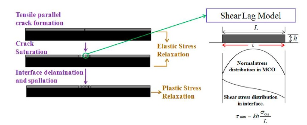
Fig. 2 Mechanism of elastic and plastic stress relaxation during experiment.
Fig.2 schematically illustrates the failure of the coating under tensile loading. Initial cracks are produced in the coating when the tensile stresses exceed the tensile strength of the brittle coating. During the rest of the experiment, tensile stresses are not transferred to the segments of coating directly from bend fixture. However the tensile stresses are transferred from the ductile substrate to the coating segments through interface as interfacial shear stress (shear-lag). As a consequence of transfer of stresses, tensile stresses continue to develop in the coating layer, creating further parallel cracks. The formation of multiple parallel cracks can be modeled as an elastic stress relaxation and cracking continues with strain until saturation. From the shear lag model, the shear stress at the interface can be calculated from the following equation [15], [16]:
where aox is the tensile oxide strength, t is the interfacial shear stress, h is the oxide thickness, L is crack spacing, and k is an integration constant which depends on the shear stress distribution along the interface. A sinusoidal shear stress distribution is assumed in the present analysis which results in k = -rc. Upon measuring the saturation crack spacing, it is possible to calculate the interfacial shear strength using Equation (1). The tensile oxide strength is calculated from the strain at which the oxide scale first cracks. The first energetic AE hit is assumed to correspond to the failure strain of the coating.
At higher strains (greater than 0.5%) the ductile substrate begins to undergo plastic deformation. The plastic stress relaxation can be modeled as interfacial slip and delamination and substrate yielding at the base of the parallel coating cracks [13]. Also at higher strain the coating spalls due to the effect of Poisson ratio which introduces compressive stress normal to the applied stress on the substrate. In the present work, it is assumed that the coating is perfectly adhered to the interconnect and is elastically strained during the experiment. This leads to the developing of elastic energy storage in the coating. Beyond a certain point, it is energetically favorable to release the stored elastic energy as interfacial fracture, resulting coating spallation. The interfacial fracture energy, G can be calculated from the relation [17]
where W is stored elastic energy in the coating per unit volume and h is coating thickness. W is a function of residual stress and stress-strain evolution on coating during the experiment. During the elastic deformation of the substrate, the compressive stress generated in the coating is calculated by
During the plastic deformation of the metal interconnect; the compressive stress is increased by the following relation:
where ^is elasticity, i/is Poisson ratio, and £ is strain. Subscript ‘c’ stands for coating and subscript’s’ stands for substrate. Finally the stored elastic energy in the coating, W is calculated from the simple relation
During the plastic stress relaxation the crack spacing remains constant (saturated) as the shear stress at the interface exceeds the shear strength of the interface.
Results and Discussion
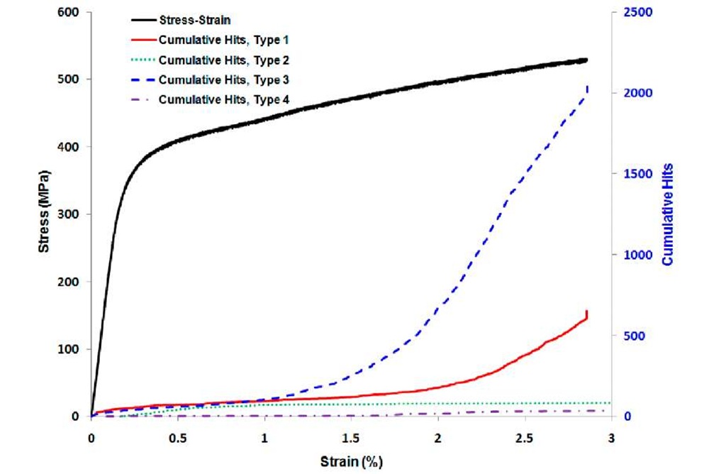
Figure 3 presents a typical stress-strain curve of a coating-interconnect composite system obtained from the load-frame data along with characteristic synchronized AE data for each specimen type. The AE data provides indication of cracking events. In Fig.3, for each type of specimen, cumulative AE data is observed to increase with imposed composite strain up to approximately 0.1% strain. The increasing nature of AE data in this phase denotes the formation of transverse parallel cracks on the coating as a consequence of stress transfer from substrate to the coating according to shear-lag theory. This phase is modeled as elastic stress relaxation. The flatness of AE nature in the next phase indicates the saturation of parallel cracks due to interface slipping or yielding. Measuring the spacing between parallel cracks in this phase, it is possible to calculate interfacial shear strength from equation 1. Interfacial shear strength indicates the capability of load transfer from substrate to coating through interface. The stronger the bond between coating and interconnect, the more the load is transferred through interface.
Fig.3 Stress-strain curve with synchronized AE data.
A distinct phase of AE data is seen when considering oxidized specimens (Type 1 and Type 3) during plastic stress relaxation (about 1.5-2% strain). In this phase, a sharp increase in the rate of AE events with strain is occurred. This sudden increase of AE events is not present for reduced specimens (Type 2 and Type 4). The higher rate of AE hits with strain indicates extensive interface delamination and spallation of oxidized specimens. Analyzing the AE data in this phase reveals decreased interfacial adhesion due to oxidation. Depending on the alloy composition of interconnects; different alloyed oxides are formed between MCO coatings and interconnect which are brittle in nature. The brittleness of alloyed oxide promotes more interfacial fracture and spallation as compared to reduced specimens.
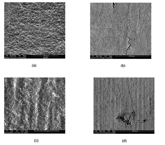
Fig.4 SEM images of transverse parallel cracks at approximately 3% strain. (a) Type 1 (b) Type 2 (c) Type 3 (d) Type 4.
Table 1: Average interfacial shear strength for each type of specimen.
|
Case |
Minimum Shear Strength (MPa) |
Maximum Shear Strength (MPa) |
Mean Shear Strength (MPa) |
Standard Deviation (MPa) |
|
|
1 |
Oxidized MCO-Crofer |
1.27 |
6.64 |
2.25 |
0.9114 |
|
2. |
Reduced MCO-Crofer |
500.88 |
620.7 |
905.27 |
242.36 |
|
3. |
Oxidized MCO-SS441 |
1.854 |
36.63 |
18.49 |
7.0565 |
|
4. |
Reduced MCO-SS441 |
382.38 |
1234.3 |
751.81 |
182.26 |
Fig.4 shows the SEM micrographs of saturated transverse parallel cracks formed in each type of specimens. Using crack spacing measurements, the interfacial shear strength was calculated from equation 1 and tabulated in Table 1. The interface between Crofer substrate and MCO in the oxidized condition has the lowest interfacial shear strength and in the reduced condition has the strongest interfacial shear strength. It is also observed from Table 1 that Type 1 specimens have more uniform shear strength at the interface as indicated by their lowest standard deviation whereas shear strength is least uniform for Type 2 specimens.
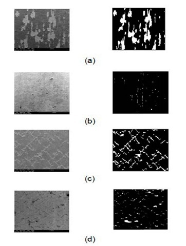
Fig 5 SEM (left) and processed (right) images of spalled surfaces at 3% strain (a) Type 1 (b) Type 2 (c) Type 3 (d) Type 4.
Scanning Electron Microscopy (SEM) was performed on the cracked coating surfaces for each type of specimen. The SEM images were processed to measure the percentage of total spallation area. In Fig.5, the SEM images and their corresponding processed images are presented for each type. In the processed images, the white portions denote spalled areas whereas the black portions indicate the unspalled coating. The measured values of percentage of spallation area and fracture energy are tabulated in Table 2. From Table 2, it can be concluded that oxidized MCO-Crofer substrate has the lowest interfacial fracture energy with maximum spallation whereas the reduced MCO-Crofer system shows the strongest adhesion with minimum spallation.
Table 2: Interfacial fracture energy for each type of specimen.
|
Type |
Onset of Spallation Strain (%) |
Interfacial Fracture Energy (J/m2) |
% Spallation Area |
|
|
1 |
Oxidized MCO-Crofer |
2.4 |
9.2-17.45 |
18.88 |
|
2. |
Reduced MCO-Crofer |
1.6 |
11.29-81.84 |
0.66 |
|
3. |
Oxidized MCO-SS441 |
1.5 |
21.13-85.05 |
9.43 |
|
4. |
Reduced MCO-SS441 |
1.6 |
15-71.16 |
3.23 |
Conclusions
Four point bend experiments were performed on both oxidized and reduced spinel MCO coated Crofer and SS441 SOFC interconnects. The present analysis reveals the significant impact of oxidation on both interfacial shear strength and interfacial fracture energy. The formation of brittle alloyed oxide weakens the interface. As a result, interface can transfer lesser load which is verified by lower interfacial shear strength compared to that of reduced specimen. Similar trend is found in case of adhesion of interface. Oxidized specimens show significantly decreased interfacial fracture energy than that of reduced specimen.
In reduced condition, Crofer interconnect shows to have stronger interface in both interfacial shear and adhesion due to possessing more chromium than that of SS441. Chromium contents strengthen the interface more. On the other hand, in oxidized condition formation of chromium oxide weakens the interface than that of SS441.
Future work involves the study of effect of residual stress on interfacial fracture energy and shear strength. Residual stress is an important factor for both reduced and oxidized interconnects. X-ray diffraction methods will be incorporated to validate the analytical residual stress calculations. Finally, high temperature experiments will be performed to assess the impact of temperature on interfacial shear strength and fracture energy.


