ABSTRACT
The incremental core-drilling method (ICDM) is a nondestructive technique to assess in-situ stresses in concrete. In contrast to other available methods of in-situ stress measurement in concrete, the ICDM can quantify stresses that vary through the thickness of the concrete member under investigation, such as those due to bending or eccentric prestressing. In this method, a core is drilled into a concrete structure in discrete increments. The displacements which occur locally around the perimeter of the core at each increment are measured and related to the in-situ stresses by an elastic calculation process known as the influence function method. This paper presents the analytical and numerical techniques necessary for practical use of the ICDM, as well as results from experimental tests in which simple concrete beams were subjected to controlled loads and in-situ stresses measured via the ICDM were compared to known stress distributions. The ability of the technique to accurately measure a variety of different stress distributions is demonstrated, and practical considerations for an ICDM investigation are discussed.
INTRODUCTION
Reliable information about the in-situ state of stress in the concrete of an existing structure can be critical to an evaluation of that structure. This evaluation may be performed as part of a load rating determination, or it may be performed to determine whether repair or replacement of the structure is necessary. Often, as in the case of a beam subjected to bending or eccentric prestressing, the stresses of interest vary through the thickness of the member. For example, the bending stress in a simple beam varies as a function of the through-thickness position z, as shown in Figure 1.
Figure 1: Example of Stress Variation Through the Thickness of a Beam
The ICDM is an attractive method of in-situ stress determination because it is more general than existing methods (which cannot be used in cases when the stress varies as a function of depth [1,2, 3]), requires access only to the top or bottom of the member under investigation, and is non-destructive (i.e. it allows the structure to still perform its intended purpose). This paper describes four steps taken in the development of this method: analytical formulation, finite-element models used to calibrate the method, numerical simulations used to verify accuracy and robustness, and a series of experiments in posttensioned concrete beams designed to demonstrate the accuracy and repeatability of the technique.
ANALYTICAL FORMULATION
The influence function (IF) method has been developed over the past two decades as a method of relating non-uniform residual stresses in steel structures to strains acquired at the surface in the ASTM hole-drilling method [4,5,6,7]. The ICDM is an extension of the IF method, except that the basis for the ICDM is displacement measurement instead of strain. Because it is extension of the IF method, the ICDM is subject to several of the same assumptions made in the ASTM hole-drilling method. Specifically, it is assumed that the following conditions are satisfied for the member under investigation [9]:
1. The material under investigation can be idealized as a linear-elastic, homogeneous continuum.
2. Plane stress conditions exist.
3. The stresses under investigation vary only with respect to the through-thickness position z (i.e. they do not vary within the plane of the object).
Some experimental and analytical work has been performed to justify that these assumptions are appropriate for typical concrete structures [1, 9].
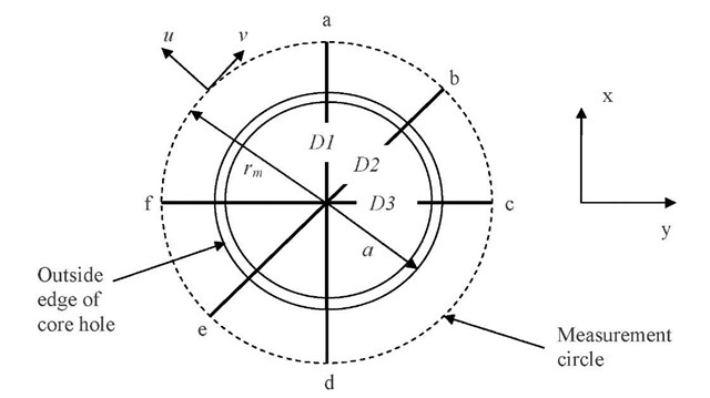
Displacements for use in the ICDM are acquired along a "measurement circle" – an imaginary circle offset from the outer edge of the core hole drilled into the concrete. The measurement circle used for this work is shown in Figure 2:
Figure 2: Measurement Circle
A Cartesian reference frame is defined at the center of the core hole of outside radius a, with the x-axis typically aligned with the longitudinal axis of the member under investigation. The measurement circle is defined by radius rm, which is typically on the order of 25 mm larger than the outside core-hole radius a [1, 2]. For simulation and calibration of the core-drilling technique, a is typically taken as 75 mm and the core hole width tb is taken as 5 mm, reflecting the radius and blade thickness of commonly-available coring bits for concrete [9, 10]. For convenience, displacements along the circle are measured in terms of their radial (u) and tangential (v) components. Although many different measurement configurations are possible [8], the current work is based radial displacements at the six points labeled a through f in Figure 2. To make the IFs for the ICDM as general as possible and to reduce the number of units in calculations, it is convenient to measure through-thickness position in terms of normalized depth H, where H=z/rm.
The ICDM is formulated in terms of mean or equibiaxial stress P, deviatoric stress Q, and shear stress component t, because any two dimensional plane stress distribution can be expressed in terms of these components. In the ICDM, each of these components is considered separately and is assumed to be a function of through-thickness depth H. The following notation is used to denote this in terms of Cartesian stresses:
Once these functions are known, any general stress distribution can be represented by superimposing these components. The variation through depth can be fit as a linear or higher-order function, although most problems of interest are best fit as either a constant or linear variation [9, 10]. If a linear variation is assumed, the variation of stress with depth is referred to as the stress gradient.
Influence functions (IFs) provide the solution for these stress functions by correlating displacements found during the coring procedure to in-situ stresses. A complete description of the influence function method as applied to the ICDM is available [8, 9, 10]; only the basic concepts are described here.
Within an infinitesimally small increment at H, the IF GA provides the relieved radial displacement that would occur under a unit equibiaxial (P=1) stress field if the core depth is h:
The core hole depth h is also normalized to the measurement circle radius. As the core hole is drilled in successively deeper increments, the total relieved displacement is due not only to the relieved displacement in that increment, but also in previous increments. Therefore, the total displacement at a particular hole depth is the summation or integral over all the increments up to that point. Displacement and stress are then related by the integral of the IF. This can be written as:
IFs for relating both deviatoric stress Q and shear stress Txy to radial displacement can be developed in a similar manner. However, because deviatoric stress and shear stress in a core hole are not axisymmetric, the displacement patterns they produce are not constant around the measurement circle but are sinusoidal functions of angular position around the measurement circle:
where 6 is the angular position of the point being measured, measured from the x-axis and GB is the influence function. An IF relating tangential displacement to deviatoric and shear stress can also be formulated [8, 9], but was not used in the current work. Because the IFs do not lend themselves to analytical formulation, it is convenient to use a matrix of IF coefficients so that the value of the IF at a particular core depth can be determined. This can be represented by a double-power expansion. For example, the mean stress radial displacement IF GA is:
where a is a matrix of influence function coefficients with row and column indexes k and l. The IF for radial displacement due to deviatoric and shear stresses GB can be similarly represented.
DETERMINATION OF IF COEFFICIENTS BY FINITE ELEMENT SIMULATION
The first step in the ICDM process is to determine these matrices of IF coefficients relating mean stress to radial displacement (a) and shear and deviatoric stress to radial displacement (ft). This is accomplished by finite element analyses in which the core drilling process is simulated by removing layers of elements in a simulated structure. These analyses are described in detail in [10]. In the analyses, the core hole is loaded from the inside, resulting in displacement at the measurement circle. The displacements vary as the core-hole depth and loading depth change, and the influence function coefficients are calibrated from these displacements. The influence function coefficients calculated in this manner can then be used in the reverse process: the calculation of in-situ stresses from known displacements.
To produce the matrix of relieved radial displacements due to mean stress uRp, an axisymmetric finite element model was employed. 25 partial core depths were simulated, with a maximum core depth of 150 mm. To produce the matrix of relieved radial displacements due to deviatoric stress uRq and the matrix of relieved tangential displacements due to deviatoric stress vRq, an analogous 3D finite element model was employed. To determine the IF coefficients, the stress within each layer of elements is set to unity. The relieved displacement at the measurement circle due to unit loading can be expressed as:
These two equations are solved for the matrices of IF coefficients a and p based on the matrices of displacements calculated by FE analysis uRp and uRq. As shown by the presence of the elastic modulus E in the previous equations, the IF matrices developed using models with one elastic modulus can be adapted for use on a concrete structure with any elastic modulus by simple scaling. Another consequence of this formulation is that accuracy of the calculated in-situ stresses is directly related to the accuracy to which the elastic modulus of the structure can be estimated.
NUMERICAL VERIFICATION
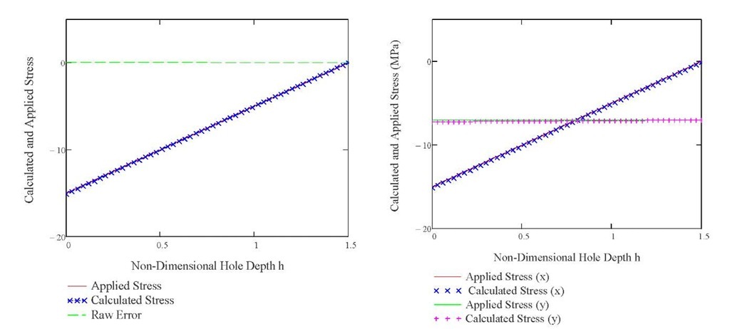
A number of measures have been used to verify the numerical accuracy of the IF solution [9,10], but the method is best tested by using displacements acquired from FE simulations of a core-drilling procedure in which calculated stresses can be compared to applied stresses. To do this, a 3D FE model similar to that used to calibrate the IF matrix ft was used. Two examples are presented here: one with a linearly-varying stress in the x-direction only (ayy, Txy=0), and one with a linearly-varying stress in the x-direction and a constant stress in the y-direction (txy=0). These models are representative of beams or plates under simultaneous bending and prestressing in one or two directions.
At minimum, a set of three displacements must be acquired at each coring depth, so that each of the unknown stress components (P, Q, and Txy) can be computed. For both of these examples, a set of three radial displacements at 0 =0°, 45°, and 90° were acquired along a measurement circle of rm=100 mm at non-dimensional core depths of 0.75 and 1.5. The stresses calculated from these displacements and the applied stresses are shown in Figure 3:
Figure 3: (a) Uniaxial Stress axx (b) Biaxial Stresses axx and a. yy
The maximum error in the calculation of any of these stresses is less than 3% when compared to the average stress in that direction. These verification examples indicate that the IF solution is capable of highly accurate prediction of both uniaxial and biaxial stresses with constant and linear distributions.
EXPERIMENTAL VERIFICATION
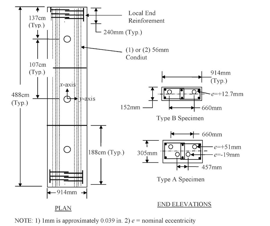
To verify that the ICDM can be used to calculate in-situ stresses in real concrete structures, a total of nine tests were conducted on three experimental specimens. The experimental program is described in detail in [17]. Each specimen was an unreinforced concrete beam approximately 488 cm in length, loaded by eccentric post-tensioning bars, as shown in Figure 4:
Figure 4: Specimen Details
The objective of the testing was to measure the stress in the top fiber of the beam and the variation of stress through the depth of the beam. The variation of stress with depth was assumed to be linear, and the variation of stress was referred to as the stress gradient. Two Type B specimens and one Type A specimen were tested to determine whether a single set of IF coefficients would produce accurate results, or whether calibration of the coefficients to the particular thickness of the member under investigation is required.
Because displacements due to core-drilling water and shrinkage can create "apparent" stresses that affect the accuracy of the technique [15, 16], the specimens were kept saturated from the time of casting to immediately before testing. In a practical application of the technique, the effect of core drilling water and shrinkage would need to be compensated for either by saturating the member under investigation prior to testing, or by quantifying and removing the apparent stresses from the solution by accounting for the concrete volume change due to water movement. Simulating the change in concrete volume by FE simulation and removing the calculated displacements from the measured displacements is one method for removing apparent stresses [16].
Specimens were cast using a concrete mix with a water/cement ratio of 0.41 and a 28-day design strength of 45MPa (6500psi). The specimens were cast on top of a double layer of plastic sheeting to ensure that the beams were not restrained by the form base. The tops of the specimens were screeded flat using the top of the forms and then given a smooth steel-
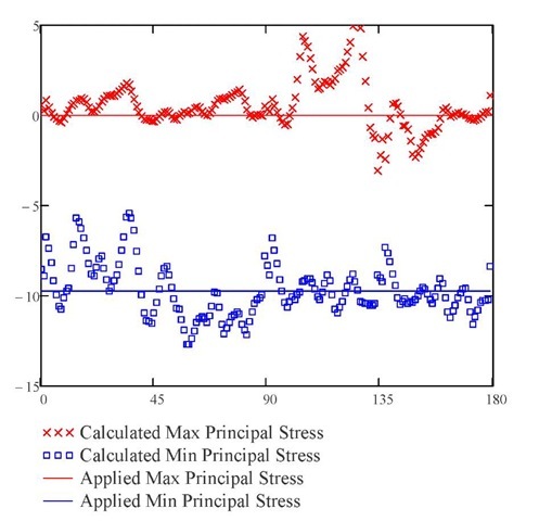
Figure 6: Typical Calculated and Applied Stress at the Top Fiber
Calculated stress gradients showed a similar clustering [17]. The 180 solutions were averaged for each of the nine tests and compared to the applied stresses. The results are summarized in Table 1:
Table 1: Summary of Calculated and Applied Stresses
|
|
Applied Top |
Meas ured Top |
|
|
|
|
|
|
Fiber Stress 01 |
Fiber Stress 01 |
|
Applied Gradient Measured Gradient |
|
|
|
Core |
(MPa) |
(MPa) |
Error (%) |
(MPa/hmax) |
(MPa/hmax) |
Error (MPa/hmax) |
|
1 |
-14.05 |
-12.43 |
11.5% |
6.87 |
7.55 |
0.67 |
|
2 |
-15.04 |
-13.90 |
7.5% |
8.21 |
10.16 |
1.95 |
|
3 |
-16.08 |
-15.29 |
4.9% |
9.61 |
11.17 |
1.56 |
|
4 |
-10.22 |
-9.08 |
11.2% |
3.79 |
2.90 |
0.88 |
|
5 |
-9.74 |
-9.06 |
6.9% |
3.18 |
2.81 |
0.36 |
|
6* |
– |
– |
– |
– |
– |
– |
|
7 |
-8.87 |
-8.28 |
6.6% |
2.92 |
2.01 |
0.91 |
|
8 |
-4.53 |
-3.66 |
19.2% |
-0.08 |
-1.86 |
1.79 |
|
9 |
-8.83 |
-7.76 |
12.2% |
2.90 |
2.83 |
0.08 |
|
Average: |
10.0% |
4.68 |
4.70 |
1.03 |
||
|
Top Fiber |
Gradient |
|||||
|
Total Average Error: |
10.0% |
21.8% |
||||
|
* omitted from averages |
||||||
|
NOTE: 1 MPa equals about 0.145 ksi |
||||||
The Stage 1 image for Core 6 was mistakenly overwritten, so measurement of relieved displacements and calculation of in-situ stresses was not possible. Error in top fiber stress was taken as the absolute difference between the applied and measured top fiber stress divided by the applied top fiber stress. Total average error for the top fiber stress was taken as the average of the percent error for each test. In each of the tests performed, the measured top fiber stress was less than the applied top fiber stress. This type of error is consistent with underestimation of the in-situ elastic modulus.
The accuracy of the measured stress gradient was generally lower than that of the top fiber stress. However, the numerical value of the stress gradients were relatively small in the specimens tested (essentially 0 for test 8). The total average error in the stress gradient (taken as the average error divided by the average applied stress gradient) is 22%. However, the average applied gradient and the average measured gradient agree to within 1%. This suggests that the measured stress gradient in a single test would be expected to be accurate to within about 20%, but that the average of multiple tests would be significantly more accurate. No significant improvement in accuracy was found using IF coefficients calibrated to the geometry of the Type A specimen.
SUMMARY AND CONCLUSIONS
The ICDM calculates in-situ stresses in concrete from measured displacements based on the well-established influence function method. The proposed influence function coefficients can accurately calculate in-situ stresses based on displacements from finite element simulations of a core drilled incrementally into a concrete structure. The ICDM can accurately determine in-situ stresses in simple concrete structures. The calculated accuracy is about 10% for the stress at the surface of the concrete and about 20% for the variation of stress with depth.


